We have previously published articles* describing electric circuits which can be used to indicate when the voltage of a power source (for example, a battery bank) either reaches a certain point, or falls below a certain point.
* Read Make a Simple Battery Status Monitor, TL431 Battery Voltage Monitor.
This article will introduce plans for a simple voltage status monitor built around the LM741 operational amplifier. These circuits are the best we have found in terms of accuracy, simplicity of operation, and cost.
LM741 Operational Amplifier
The LM741 is an operational amplifier. The wide range of uses of this simple and cheap integrated circuit do not need to be mentioned here – of importance is that an output voltage is turned on (or off) automatically when a measured voltage (e.g from a battery) reaches the same value as a reference voltage (manually set by the user).
Therefore, if we want an LED to light up when a solar battery charger reaches a certain voltage for example, we can achieve this with an LM741.
The LM741 specification sheet can be downloaded here. You can buy LM741 chips in the REUK Shop.
LM741 High Voltage Indicator
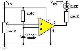
The circuit diagram shown above is configured to give a high voltage indication – LED turned on when the measured input voltage is above a certain level. The 100KOhm variable resistor is used to manually configure the voltage over and above which the LED will light.
If the reference voltage arriving at pin 2 of the LM741 is lower than the battery voltage arriving at pin 3 via the voltage divider created by the variable resistor, then the output from pin 6 of the LM741 will be low. Therefore the LED will turn on as it has voltage across it.
If on the other hand the reference voltage on pin 2 is higher than the battery voltage on pin 3, the output from pin 6 will be high, and so as there is no voltage across the LED, it will be off.
The Zener diode should be chosen with a zener voltage of around half that of the target voltage – e.g. for a 12.0 Volt indicator, a 5.6 Volt Zener diode could be used.
LM741 Low Voltage Indicator
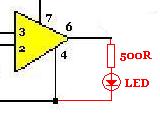
In order to obtain a low voltage indication – useful if you would like to stop using a battery before it is drained too deeply – the output from pin 6 is still directed through an LED (and current limiting resistor), but this time it is connected to ground (0V) rather than to the positive input voltage Vin as shown in the amended circuit diagram above.
The output from the LM741 will still be the same as with the high voltage indicator described above: pin 2 voltage lower than pin 3 voltage results in a low output from pin 6, and pin 2 voltage higher than pin 3 voltage results in a high output from pin 6. Since the LED now goes to ground, a high output from pin 6 sees it turn on, and therefore we have our low voltage indication with the battery voltage on pin 3 lower than the reference voltage on pin 2.
Note that these circuits will only operate with input voltages in excess of around 3.8 Volts and so cannot be used with a 2 AA battery charger for example.
NEW For an LM741-based circuit plan for a low voltage indicator specifically for a typical 12 Volt battery or battery bank, click here to read our article 12 Volt Low Battery Indicator – LM741.
Configuring the Voltage Indicator
In order to set up the voltage indicator a variable power supply unit should ideally be used. Using a digital multimeter set the voltage to the desired light up LED value, connect the voltage source to the circuit, and then turn the 100K variable resistor until the LED is just turning on/off. It is now configured to light up (or turn off) the LED at that exact voltage.
If you do not have a variable voltage source – as is the case for most people – then you need to find a way to supply the desired reference voltage to the circuit for configuration. If for example, you want to light up the LED when a solar battery charger has fully charged some batteries, connect fully charged batteries to the solar panel and then connect the whole thing to the circuit while you adjust the 100K variable resistor.
Similarly if you want the LED to light up when a 12V lead acid battery is 25% discharged (i.e. you measure a terminal voltage of 12.00V on the battery), then wait until your battery has discharged approximately this far and then set up the indicator circuit.
Another alternative is to use a variable voltage regulator such as an LM317 (LM317 Adjustable Voltage Supply) to get the desired threshold voltage for calibration of the voltage indicator.