Line Losses Calculator
Line Losses Calculator
An automatic calculator to work out line losses in DC powered systems
home > storage | generalIn our article Minimising Line Losses in RE Systems we looked at how the diameter of wire (cable) should be selected to ensure that line losses (i.e. energy lost when the current flowing through a wire heat it up) are kept below 10%.
If you are interested in understanding the equations which are used to make the calculations below, then we recommend you read the article linked to above.
Wire Size Calculator
Enter the peak charging voltage (volts DC - e.g. 14V to 20V for a 12V rated wind turbine), wire length (metres), peak current (Amps), and maximum acceptable power loss (%, we suggest 10% or lower), and click Calculate to view the minimum cross sectional area of the wire you should use.To convert the above wire cross sectional area to AWG, mm diameter, or inch diameter, click here to go to our Automated AWG Wire Size Converter. Remember to choose a wire with a slightly larger cross sectional area than that recommended above to ensure that power losses are below your maximum acceptable percentage.
Line Losses Calculator
Alternatively use the calculator below to work out the line losses for a system with a given wire size (diameter measured in mm).Comment on this Article
If you have any comments on this article, please email them to neil@reuk.co.uk.Related Articles and Products
More from the REUK.co.uk website:| Low Voltage Battery Disconnect Circuits Find out more about low voltage battery disconnect (LVD) circuits - used to protect batteries  | Equalization Charge Find out about the equalization charge for lead acid batteries  | Make a Simple Battery Status Monitor Monitor battery status with this easy electric circuit project - no skill required!  | Buy a 12v Power Supply Unit Find out more about 12V mains transformers and power supply units  |
| Amperor 12 Volt LCD TFT Stabiliser A 12V regulator for use with flat screen televisions and more  | Build a Battery Shed Battery banks like to be stored in the warm and dry - so build a power shed!  | What Are Ultracapacitors Find out about ultracapacitors - how they work and what they are used for. 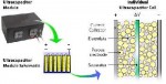 | LM2940 12V 1A Low Dropout Regulator Find out how to use an LM2940 to efficiently regulate voltage 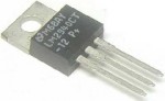 |
storage, general.