In our article titled PIR Sensors we introduced passive infrared (PIR) sensors and summarised their uses. Of particular interest to us are 12 Volt DC powered PIR sensors and associated circuits since these can be powered directly from a 12 Volt battery which is in turn charged by wind, solar, or other renewable energy sources.

In this article we will look at the ways in which the excellent low current consumption Honeywell IS-215T* 12 Volt DC PIR sensor (available in the REUK Shop) can be used by the renewable energy enthusiast for lighting, security, and other motion detection systems. There are many other home security PIR sensors from other manufacturers which have the same mode of operation as the Honeywell unit, so the following circuits and details will still be applicable with those.
* Click here to download the Honeywell IS-215T datasheet for all the technical specifations, range, and applications for this PIR sensor.
Inside the 12 Volt PIR Sensor
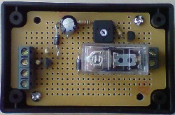
When the cover of the PIR Sensor unit is popped off it appears as shown below. A row of terminal strip at the top right of the circuit board is used for making the necessary connections – two connections to provide power to the unit (labelled + and -) and two for the internal relay (labelled C and NC). The ‘C’ is short for Common, and the ‘NC’ for Normally Closed.
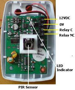
The most important thing to note about the vast majority of home alarm system PIR sensors is that they output a HIGH signal when motion is NOT being detected, and no signal at all when it IS being detected. Why are they designed this way? Because if there was no signal at all when motion was not being detected, a burglar could simply cut the cables leading into the security alarm controller, and then when the signals went high when a PIR detected motion, the controller would not receive those signals and the alarm would not be triggered. With a high signal when motion is not detected, if any cables are cut or if motion is detected no signal will get to the controller and the alarm will be triggered immediately.
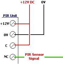
The ‘C’ and ‘NC’ screw-in terminals on the PIR sensor are connected to the terminals of an internal relay, and the positive of the 12V power supply is connected to the ‘C’ terminal. While motion is not being detected (or if a burglar cuts the power to it), the PIR sensor leaves the relay open meaning that ‘C’ and ‘NC’ are internally connected to one another (shorted). Therefore a high signal (positive 12V) comes out of the ‘NC’ terminal which is then connected to the alarm system (or used in your motion sensing application). When motion is detected, the relay is closed, ‘C’ and ‘NC’ are no longer shorted, and so the positive 12V from ‘C’ is no longer outputted from ‘NC’.
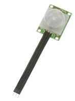
PIR modules designed for use in other non-security applications (such as the KC7783R PIR module are designed to output a high signal when motion IS detected and no signal or 0V when it is not. This makes it simpler to sound a buzzer when motion is detected for example.
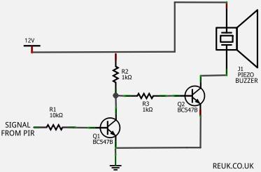
In order to get a more useful high signal when motion is detected we need to invert the output from the PIR sensor. For this we need a logic NOT gate – a device which will output a low signal when the input is high, and output a high signal when the input is low. This can easily be achieved by making a simple transistor inverter NOT gate with an NPN transistor and a couple of resistors as shown below.
 |
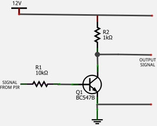 |
So, when the PIR sensor unit detects motion, the LED on the PIR sensor lights up, there is no PIR Sensor signal (low) so that is inverted to an output signal of +12V (by our simple NOT gate). When no motion is detected, the LED is not lit, the PIR sensor signal is +12V which is then inverted to an output signal of 0V (low).
The output signal can then be connected to the base of another transistor which can in turn pass current across the coil of a relay, light up a 12 Volt LED spotlight, or power a buzzer/alarm as shown below.
There is however one problem. The device (or circuit) connected to the output from the NOT gate inverting circuit will only receive the high signal for as long as the LED indicator is lit on the PIR sensor unit which is typically a couple of seconds at most when motion is detected.
If you have a light you want to be switched on and left on for a fixed time interval after someone walks past the PIR sensor, or if you want a video camera* to record for say 30 seconds every time the PIR sensor unit is triggered, then you will need a simple timer circuit.
* See our article on Solar Powered Wireless CCTV for more information on setting up such a system.
PIR Sensor Timer Relay Circuit
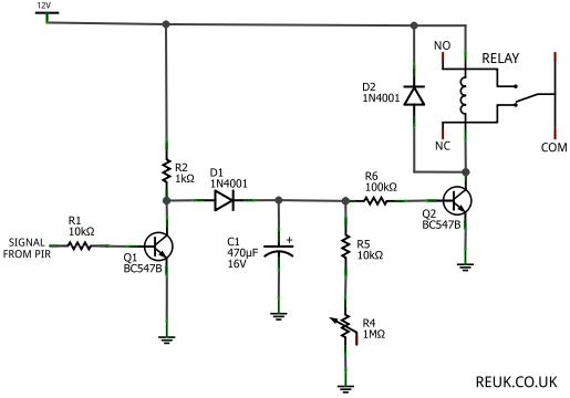
Pictured above is the schematic of the REUK PIR Relay Timer. When the 1M variable resistor is turned to 0 Ohms, the relay stays on for 4-5 seconds after motion was last detected. When the variable resistor is turned to around 1 MOhms, the relay stays on for around 75 seconds* after motion was last detected. This timer can therefore easily be adjusted within the range of 5-75 seconds as required by the particular application.
* The exact timing range of this circuit will depend particularly on the choice of relay and transistors used to build it.
If you would like to connect more than one PIR sensors into the same circuit – for example, one sensor at the front of a property and one at the rear to turn on some lights when motion is detected, click here to read our article: Multiple PIR Sensor Circuits.
Buy a Complete PIR Relay Timer Circuit
If you do not have the necessary tools, skills, time, experience, or desire to put together this type of relay timer circuit for yourself, do not worry – we sell the PIR Relay Timer as a complete unit in the REUK Shop, designed and tested for use with our PIR sensors.
Switch a Relay with a Modified PIR Sensor Lamp

Click here to view our article Hacked PIR Sensor in which we show how a <£3 PIR triggered lamp (pictured above) can be converted so that it can switch a relay when motion is detected.