In this article: Light Dependent Resistor we showed had a small light detector can be used within a circuit to turn on something (typically a light bulb) when it is dark or light. This is a very simple circuit with minimal components, however, there is one situation when things can be made even simpler: if a PV solar panel is being used to charge a battery, and you want to turn something on when it is night time – for example in garden lighting or security lighting – the solar panel itself can be used as the light detector. This is particularly useful since solar panels are already very waterproof and resilient UV light whereas light detectors tend not to be.
Solar Panel LED Driver Circuit
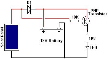
The circuit above shows how a solar panel used to charge a battery can also turn on an LED when it is dark (i.e. solar panel not generating) with the addition of a couple of resistors, an LED, and a PNP transistor.
In our article What is a Transistor we showed that a transistor is an electronic component which can be used to control a relatively large amount of current with a relatively small current in the same way that turning a small valve on a water pipe will allow a large amount of water to flow through the pipe. In the vast majority of our projects we use NPN transistors. These allow current to flow between the collector (C) and emitter (E) of the transistor only when a small current is being applied to the base (B).
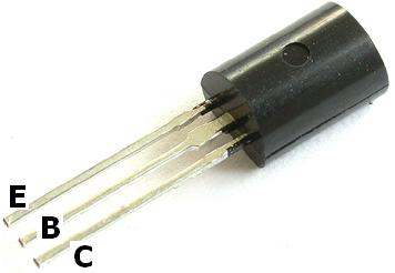
In this light/dark detecting circuit, we instead use a PNP transistor. This component does the opposite of the NPN – i.e. current is allowed to flow between the collector and emitter except when there is current being applied to the base.
So, in the above circuit, when the solar panel is generating, current flows from the positive output of the solar panel through the 10K resistor and into the base of the PNP transistor which prevents current flowing from the collector to the emitter and so the LED is turned off.
When the solar panel is not generating (e.g. at night), no current flows into the base of the PNP transistor and so the positive of the battery is connected via the collector and emitter to the LED. Therefore the LED is turned on.
The diode (labelled D1) prevents stored battery charge from escaping through the solar panel at night (dark current). Without it this light/dark detector would not work since the positive of the battery would be permanently supplying current to the base of the transistor keeping the LED turned off. A Schottky Diode is best for this job since it takes around half as much power as a standard silicon diode.
The 1K8 resistor (1,800 Ohm) is there to protect the LED from being burned out by too much current since it requires just a couple of volts, but in our example schematic the power source is 12V. The 10K resistor (10,000 Ohm) is there to limit the current going into the base of the transistor.
Modifications
To modify this circuit for a lower voltage solar panel and battery you just need to change the values of the two resistors – for example for a 6V solar panel charging a 4AA battery pack, the 10K could be changed to 5K and the 1K8 to something around 1K depending on the specs of the LED and how bright you want it to be.
Instead of an LED, this circuit could be used to control a relay which could in turn switch anything (subject to the limitations of the chosen relay). However, a more complex circuit should really be used in this case so that the output does not multi-switch (turn on and off repeatedly and rapidly) during the transition from light to dark and back again – for example: light dark sensor circuit relay, or REUK Super LDR Dusk/Dawn Relay Controller.