Our REUK Programmable Low Voltage Disconnect (LVD) is a product which is used to protect batteries from being excessively discharged and therefore permanently damaged. The user of this device can set the voltage at which the low voltage disconnect is activated, and a second higher voltage at which it is cancelled.
In programming mode, each button press reduces the low voltage by 0.1V from a default value of 12.5V, or increases the cancellation voltage by 0.1V from a default value of 12.0V. For example, they would press the button 7 times to set the low voltage to 11.8V (12.5-0.7V) or 9 times to set the cancellation voltage at 12.9V (12.0+0.9V).
This method of user data entry works very well as it is simple and much cheaper than using a digital display or digital keypad BUT where it does not work so well is in situations where the low voltage is to be set very low, or the cancellation voltage very high – for example, to set a low voltage of 10.0V would require 25 button presses. That is not convenient, and so many button presses increases the likelihood of the user making a mistake.
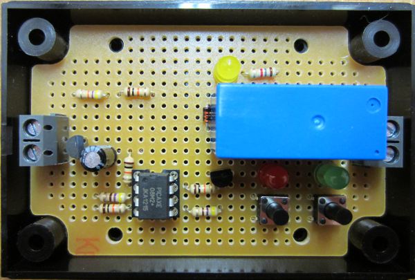
To get around this occasional issue we have come up with an alternative design (prototype pictured above) which enables the user to enter the voltage set points using binary via a couple of buttons with corresponding red and green LEDs.
Let’s say someone wants to set the low voltage set point to be 12.4V. Removing the decimal point gives us 124 which is 1111100 in binary (just type a number followed by ‘in binary‘ in google to find out its binary value). The user enters this binary value pressing the red button for a ‘0’ and the green button for a ‘1’. The LEDs then replay the sequence of 1’s and 0’s for visual confirmation of correct data entry, and that’s it – the unit is programmed.
More Technical Detail
We were going to use an 8-bit value for the voltage entry, but that gives a maximum value of binary 11111111 which is 255 in decimal. Since we want our LVD’s to be suitable for 24V battery systems without software modification, 25.5V is almost always going to be too low and so 8 bits is simply not enough. Therefore we changed the design to 16-bit (maximum decimal value 65535) but this means that for the expected maximum voltage of 30.0V we have for the decimal value of 300 a 16-bit binary value of 0000000100101100. This has a lot of leading zeroes which again increases the chance of the user making a mistake – therefore in the final design the user enters the binary value starting with the least significant bit (i.e. going from right to left) and any leading zeroes (which are now following zeroes) are added automatically by the microcontroller.
For example, if a user with a 24V battery system wanted a cancellation voltage of 27.4V, they would type in the Google search box convert 274 to binary and get the following result:
The leading 0b just tells you that what follows is in binary – 100010010. The user then uses the red and green buttons to enter this binary value starting from right to left 0-1-0-0-1-0-0-0-1, and that is it – 27.4V has been successfully saved in the device.

