Additional Information
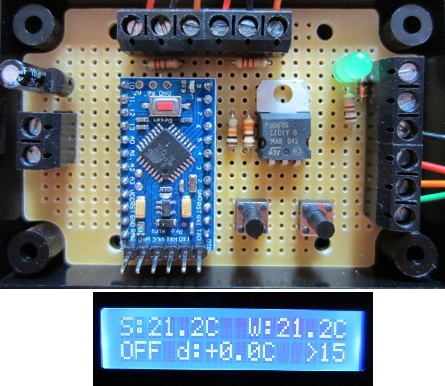
This is our new 2014 REUK Solar Water Heating Pump Controller with LCD Display. Functionally very similar to our popular 2013 Controller, this new controller has the added benefit of a 16×2 backlit LCD to display the temperatures measured of the solar panel and of the water being heated, as well as displaying system status and set up information.
This controller can be used to control a circulation pump which pushes water through a solar collector (solar water heating panel) to heat the contents of a domestic hot water tank, swimming pool, hot tub, etc.
NEW – We have now updated this controller at no extra cost. Details are available here: 2016 Solar Pump Controller with LCD Display and Datalogger. The new device offers all the features of this 2014 controller, but with the added benefit of a built in datalogger.

The controller is supplied with non-waterproof temperature sensors (details below), but we also have waterproof temperature sensors available which can be used interchangeably. Please email neil@reuk.co.uk if you require one or both of your sensors to be waterproof as there is a small supplement to pay for waterproof sensors.
Powering the Controller
This is a 12VDC powered device (10V to 15V), and so should be powered either by a solar charged or otherwise 12V battery or with one of our mains plug-in 12VDC power supplies. You cannot power this controller directly from a 12V charging solar panel as the controller needs a reliable constant supply, and a ’12V’ solar panel can easily output up to 21V.
The Temperature Sensors
For the 2014 Solar Water Heating Pump Controller we have chosen to use digital DS18B20 temperature sensors. These give excellent accuracy and reliability, and are also readily available in a good quality fully waterproof version with 1 metre long leads attached.

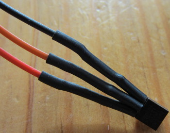
The standard (non-waterproof) DS18B20 sensors are provided pre-soldered to 100mm insulated leads. The soldered joints are covered with heat-shrink tubing to prevent short circuits and protect against corrosion. One temperature sensor is for the solar water heating panel, and the other for the hot water tank (or pool etc).
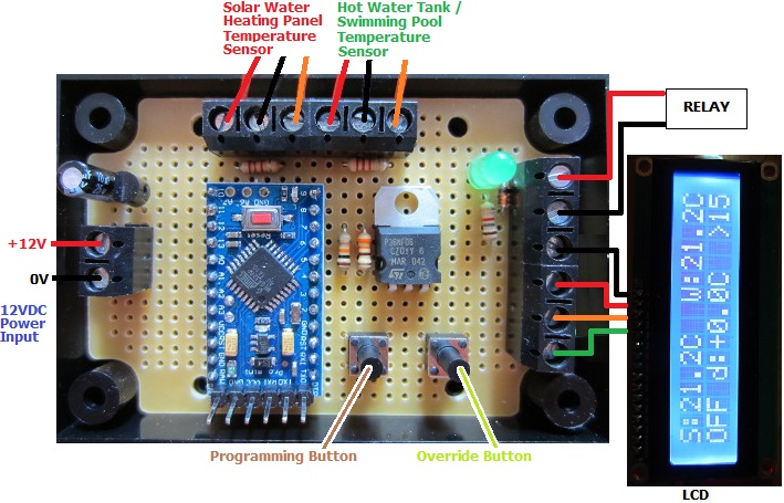
Some terminal strip is provided to enable you to connect the sensor leads to the long cables (not included) which you will use to connect your solar heating panel sensor, water tank sensor, and this control circuit.
The first temperature sensor should be stuck to the copper pipe just where it leaves the solar heating panel. The second should be stuck to the outside of the hot water tank underneath the insulation about one third of the way up from the bottom of the tank. We recommend that you use heat sink adhesive (also known as thermal glue – commonly used to stick heat sinks to the tops of processors in computers) to attach the sensors to the pipe and tank. This type of adhesive conducts heat very well ensuring accurate temperature readings, and it will hold the sensors securely in place ideally when used together with some electrical insulation tape.

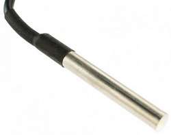
Waterproof temperature sensors (supplied on request) can be mounted similarly, but you must ensure that the full length of the stainless steel covering of the sensor is in good contact with the outside of the pipe (if they are not to be mounted within the pipe, tank, or pool in direct contact with the water to be measured) in order for them to respond quickly to temperature changes.
Controlling the Pump
Unlike the 2013 Controller, the 2014 Controller is not supplied with an onboard relay. Instead there is a 12VDC output rated at up to 1 Amp supplied when the pump is to be ON. This output can then be connected across the coil of a relay of your choosing to actually do the switching of the pump. This can be a PCB type relay, a relay board, an automotive relay, or a solid state relay (SSR) according to your own requirements.
The Display

In standard operation the display pictured above shows the following:
S is the temperature measured at the outlet of the solar water heating collector at the position of the first sensor.
W is the temperature of the hot water – hot water tank, pool or whatever – at the position of the second sensor.
ON or OFF is the status of the pump.
d is the measured temperature difference between the solar panel and the hot water. A positive value means that the solar panel is hotter than the stored water.
>10 for example means that the pump will next turn on when the temperature difference exceeds +10C for 15 seconds continuously.
<4 for example means that the pump will turn off again when the temperature difference falls and remains below +4C for around 10 seconds continuously.
The sensor temperatures are measured and displayed approximately two to three times per second, so increases and decreases in temperature can be observed in real time. The temperatures are displayed to one decimal place with four divisions per degree (XX.0C, XX.3C, XX.5C, XX.8C).
Setting the Pump On and Pump Off Temperature Differentials
Our controller measures the temperature of the outlet from the solar water heating panel. As the fluid in that pipe travels from the solar panel through the pipe to the hot water tank, it will lose some of its heat to the surrounding environment. The longer the run of pipe and the less well insulated that pipe is, the worse this effect will be. If we run the pump when the temperature measured at the solar panel is just 1 degree hotter than that measured in the hot water tank for example, then by the time the heated fluid gets to the hot water tank, it could well be cooler than the water already in the tank (if the fluid temperature drops by more than 1 degree Celcius in the pipe run), in which case we would actually be cooling the stored hot water if we ran the pump.
Therefore, as with our 2013 Controller, the user can set ‘temperature differentials’ – required temperature differences between the solar panel and the hot water tank before the pump will turn on and turn off. We call these two temperature differential thresholds diffON and diffOFF. diffON is the number of degrees by which the solar panel must be hotter than the hot water store for the pump to be turned on, and diffOFF is the (lower) number of degrees by which the solar panel must be hotter than the hot water store for the pump to be turned off.
With diffON at 10 degrees C and diffOFF at 4 degrees C for example, the pump will turn on after 15 seconds of the solar panel being hotter than the tank by more than 10 degrees, and will turn off again after 8 seconds of the solar panel being less than 4 degrees hotter than the tank.
To set diffON and diffOFF, press and hold the Programming Button for more than a second. The display will go blank, and then when you release the Programming Button, the display will show “PROGRAMMING MODE” and “set diffON +10C” (where the 10C will be replaced with the current saved value of diffON). Press the Override Button to increase diffON by 1, or press the Programming Button to reduce diffON by 1. Press the button(s) again and again to keep on increasing/decreasing diffON until you reach the value you want. Five seconds after your last button press, the display will change to “SAVED” followed by the newly saved value for diffON. diffON will then be stored in memory.
Note that diffON must be a minimum of 2 degrees Celcius and can be set to a maximum of 30 degrees Celcius.

Next, the display will show “set diffOFF +4C” (with 4C replaced with the current saved value of diffOFF). Again use the Override Button or Programming Button to increase or decrease the value of diffOFF to the value you want. Five seconds after your last button press, the display will change to “SAVED” followed by the newly saved value for diffOFF. diffOFF will then be saved in memory.
The value you set for diffOFF must be at least 2 degrees lower than the value you have entered for diffON (to guarantee hysteresis to prevent the pump switching on and off repeatedly quickly), and the minimum value it can be set to is 0 degrees Celcius.
diffON and diffOFF are stored in long term memory and are not lost if/when you disconnect the controller from the power source; therefore you only need to repeat this process if you actually want to change the stored values.
Manual Override
In order to force the pump to run (for example when you are testing your system) press and hold the Override Button for more than one second. The bottom line of the display will then read “MANUAL OVERRIDE” and the pump will turn on and stay on. The temperature sensor readings will continue to be updated on the screen during this override. When you wish to cancel the override, simply press the Override Button again for half a second and standard operation will resume – i.e. if the pump was already running when you pressed the override button, it will stay on, but will now be controlled by the temperature sensors; if the pump was off when you pressed the Override Button, it will turn off.
Bespoke Solar Water Heating Pump Controllers
If you require a solar water heating pump (or other) controller which operates differently from this 2014 Controller with changed or additional features, please contact neil@reuk.co.uk with details of your exact requirements; for example, if you need a maximum temperature override, or temperature datalogging.