We recently published our Arduino Solar Water Heating Pump Controller Design and Code which shows the basics of putting together a very simple solar water heating pump controller which you can then extend to add the other features you require. (Click here also for our Introduction to Arduino.)
The feature about which we have received the most questions is datalogging functionality to generate a log file of the temperatures recorded and the status of the pump (on or off).
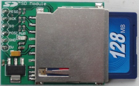
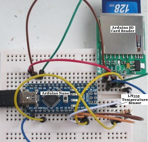
Pictured above is a demonstration on prototyping breadboard of how datalogging can be achieved using an Arduino SD Card Module (click link to buy). These are available from just £0.99 including delivery for standard SD cards (and from around £1.60 including delivery for modules for micro SD cards).
 SD card modules for Arduino are very simple to use. SD cards operate on 3.3V, but the Arduino on 5V; however, these modules have all the necessary components fitted to bring down the voltages and enable safe reliable operation without the need for you to add any external components.
In the breadboard demonstration above, we have a single LM335 temperature sensor connected to the A0 pin of an Arduino Nano as per the solar water heating pump controller design (linked to at the start of this post).
We then have the following connections between the Arduino and the SD Card module:
Arduino D10 to SS (slave select)
Arduino D11 to MOSI (master out slave in)
Arduino D12 to MISO (master in slave out)
Arduino D13 to SCK (serial clock)
We also connected the 5V and GND pins of the Arduino to the corresponding SD Card module connections to power it.
Note that some SD Card modules have their connections labelled differently.
CS=SS, DI=MOSI, DO=MISO, and CLK=SCK.
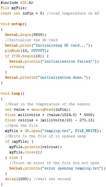
For this demonstration we just want to create a text file (called templog.txt), measure the temperature once per second, and add each temperature reading to the end of the file to form a very basic datalog.
 The stored data on the SD card can then be viewed, manipulated, and graphed on a PC. Multiple temperature sensors (or other sensor inputs) can be added and logged by extending the bare bones Arduino code above.
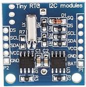
For a more advanced datalogger, the next key element to add is an RTC (real time clock). Using an RTC each data point can be logged alongside the exact time that it was recorded. Arduino RTC modules including a backup rechargeable button cell are available very cheaply. We will show you how add an RTC to an Arduino datalogger in a future post.

