Controller for Poultry Incubator

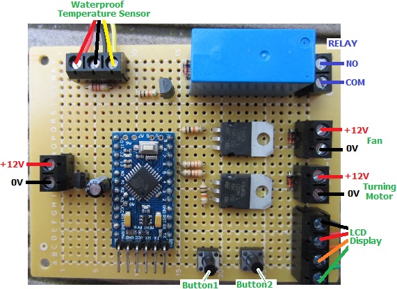
Pictured below is an automatic controller for a poultry incubator. The eggs in this incubator must be kept within a tightly regulated temperature range, they need to be automatically turned at regular intervals, and there is also a fan to be controlled.

thermostatic poultry incubator control boardThe owner of this incubator would like the temperature of the eggs to be kept between 37 and 37.5 degrees Celcius, so there is a heating element which is switched by an on board relay following the temperatures measured by a DS18B20 waterproof sensor.

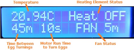
The eggs are to be turned every 30,45,60, or 75 minutes, and to do this the motor must run each time for a few seconds. Both of these timing intervals can be set by the user.

The fan has three modes of operation – on, off, or automatic, and in automatic mode the user can select an interval of 5, 10, or 15, etc minutes on and minutes off repeating.

Display for thermostatic poultry incubator controllerAll of the current settings and system status are shown on a backlit 16×2 LCD display (see above), and all user settings are programmed using this display and the two buttons on the controller board.

If you need a controller of this type, please email neil@reuk.co.uk with details of your exact requirements. For details of an alternative incubator controller which also controls humidity, click here: Poultry Egg Incubator with Humidity Sensor.

Automatic Shooting Target Time Controller

Pictured below is a controller designed for competitive shooters to automatically turn targets on the range to face to and away from the shooters for the required length of time.

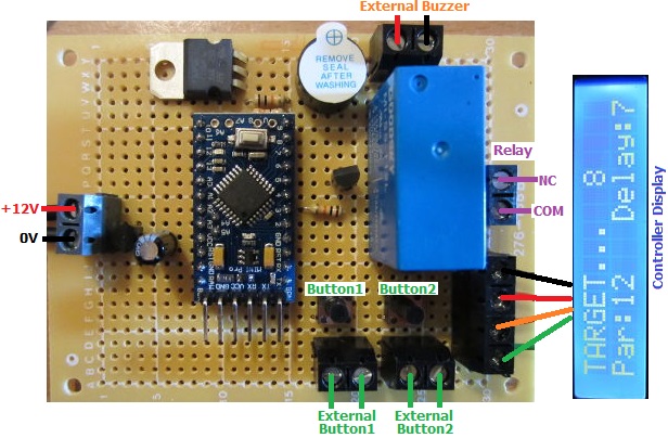
shooting-range-target-controllerThe targets are controlled by air solenoids. When these are energised the targets face away from the shooter, so our controller has a relay with NC and COM connections (normally connected). When the relay is energised, the NC-COM connection breaks and the targets turn to face the shooter.

After pressing a button to start the timer, there is a user selected delay of 3 or 7 seconds. Then the relay is energised to turn the targets to face the shooters and a buzzer sounds for half a second. The targets are kept facing the shooters for a user selected ‘par’ time of 1,2,3,4…15, 25, 35, 90, 165, or 210 seconds. Then the relay is de-energised, the targets turn away, and the buzzer again sounds for half a second. The system then resets ready to be used again.

Pressing the other button acts as an override so that the targets can be kept facing the shooter until the button is pressed again to cancel the override.

range-controller-targets-turnedAn LCD display is provided to make setting up the device with the required delay time and par time easy, and also to show a countdown of the number of seconds remaining during the two countdowns when the system has been triggered. It also constantly shows the current delay and par time settings to make the system easy to use.

We have added screw in terminals to the board so that a louder external buzzer/siren can be added, and so that external buttons can be mounted if the controller is to be housed in a waterproof box etc.

If you require a controller of this type (here is another of the competitive shooting timers we have made recently), please email neil@reuk.co.uk with details of your exact requirements.


Timer for Atlantic Crossing Balloon

Pictured below is a timer we made recently to help conserve battery power for the telemetry for an attempted balloon crossing of the Atlantic.

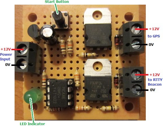
Timer for Atlantic balloon crossing telemetryThe payload of the balloon includes a GPS transmitter and an RTTY beacon so that the flight of the balloon can be tracked. Due to weight considerations, there is a limit to the size of the battery pack which can power these, and therefore there is a risk that the battery will run flat before the balloon (hopefully) lands in Europe after crossing the Atlantic from New York state.

Therefore, we were commissioned to make a secondary timer which would supply power to the RTTY beacon only for 15 minutes in every hour, and also to supply power to he GPS transmitter only when it is likely to be over land – for the first 7 hours and then again after a couple of days have passed. For this we used a PICAXE microcontroller because of its lower power consumption.

GPS module and RTTY beacon for Atlantic balloon crossing telemetry with ArduinoThe GPS and RTTY modules to be powered are pictured above connected to the Arduino Nano and Arduino Uno which control them – both relatively high power consumption devices themselves. Future flights will reduce weight and power consumption by connecting the GPS, and RTTY to a single Arduino which will also put itself into sleep mode to conserve power.

Balloon flight to near spaceWe were previously involved in an amateur balloon flight to the lower stratosphere reaching an altitude of 120,000 feet during which the picture above was taken which clearly shows the curvature of the Earth and the edge of the atmosphere. We made the timer which automatically severed the connection between the balloon and the payload after a fixed time to comply with FAA requirements.

DS18B20 Temperature Measurement with Spark Core

In our blog post Spark Core Introduction and First Impressions we introduced Spark Core – a Wi-Fi enabled Internet of Things device which can be programmed like an Arduino and accessed via the internet.

Spark Core Wi-Fi Open Source IoT development board

Of most interest to us at REUK is using Spark Core to enhance our range of solar water heating controller adding datalogging and internet functionality. Therefore we want to access temperature readings from DS18B20 digital temperature sensors of the type used in our 2014 Solar Water Heating Pump Controller connected to Spark Core.

As a test we connected a DS18B20 temperature sensor to the Spark Core. Pin 1 of the sensor connects to GND, Pin 3 to 3.3V, and Pin 2 to a digital pin on Spark Core – we randomly chose D2. Finally we connected a 4K7 resistor across Pins 1 and 3 of the sensor and entered the following code via the Spark IDE to flash to the Spark Core:

#include "spark-dallas-temperature/spark-dallas-temperature.h"
#include "OneWire/OneWire.h"
#define ONE_WIRE_BUS 2
OneWire oneWire(ONE_WIRE_BUS);
DallasTemperature sensor(&oneWire);

float temperature = 1.0;
char myStr[10];

void setup() {
 Spark.variable("read", &myStr, STRING);
 sensor.begin();
 sensor.setResolution(12);
}

void loop() {
 sensor.requestTemperatures();
 temperature= sensor.getTempCByIndex(0);
 sprintf(myStr,"%.3f",temperature);
}

At the time of writing (August 2014) it is not possible to have a Spark.variable which is a float – the code just will not compile – so the temperature measurement from the sensor (which is a float/double) must either be saved as an integer (losing accuracy due to rounding) or be converted into a string (which is what we did above to three decimal places with the sprintf function) so it can be accessed remotely.

We then wrote the following Python script on an internet connected Raspberry Pi to grab the temperature measurement once every minute and to append it to a text file for datalogging and later analysis:

#!/usr/bin/python

import urllib2
import json
import time

var = 1
while var == 1:
   response = urllib2.urlopen('https://api.spark.io/v1/devices/YOURDEVICEID/read?access_token=YOURACCESSTOKEN')
   html = response.read()
   reading = json.loads(html)
   temperature = reading['result']
   with open("core-temp-log.txt", "a") as myfile:
      myfile.write(temperature)
      myfile.write('\n')
   myfile.close();
   time.sleep(60)

The string variable read is the string conversion of the value read in by the temperature sensor.

Having got the Spark Core successfully reading data from a DS18B20 it is possible to fully replicate our Arduino based solar water heating pump controllers with the added benefit of internet connectivity and effective remote datalogging.

See our Raspberry Pi related articles Publish Temperature Sensor Readings to Twitter and Temperature Logger with Xively to find out how to automatically publish your collected data to the internet – either as a Twitter feed or with Xively as an online datalogger with graph plotting etc.

Spark Core Introduction and First Impressions

Spark Core is described as an Open Source IoT (Internet of Things)Toolkit.  It is a small Wi-Fi development board which connects automatically to servers in the cloud, and can be programmed and controlled remotely over the internet and also send data to the cloud where you can access it.
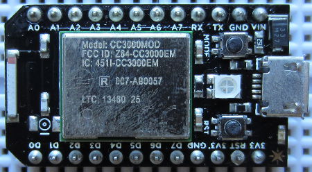
Spark Core Wi-Fi Open Source IoT development board

The Spark Core board is programmed using Wiring – the same programming language used with Arduino – but via a browser based IDE. Therefore you do not physically connect the board to your PC. Instead you just power it, it connects to your Wi-Fi automatically (with credentials entered during a one off setup process), and then automatically connects to the Spark servers. You then write your Wiring code in your web browser, it is checked and compiled on the Spark servers and the code is then flashed to your board over Wi-Fi and starts running.

Each Spark Core has a unique device ID with an associated secret access code so no-one else can take over your Core or access the data from it.

To try out Spark Core, we put together a very simple setup just to measure the ambient light level.
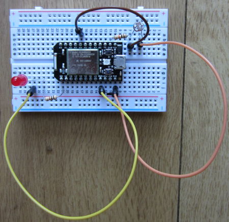
Spark Core light detector test circuit

Spark Core is supplied with its own prototyping breadboard. We connected a light dependent resistor (LDR) to one of the regulated 3.3V output pins, and to one of the ground pins via a 10K resistor. This creates a voltage divider (where the LDR meets the resistor), the output of which we connected to analog pin A4. (In the photograph above, we also have an LED connected via a current limiting resistor to digital pin D0).

The analog pins on the Spark Core are 12-bit analog to digital converters (ADC). Therefore, they measure the voltage on the pin and give it a proportional digital value from 0 to 4095 where 0 is 0V and 4095 is 3.3V.

const int ldrpin = A4;
int lightlevel = 0;

void setup(){
   pinMode(ldrpin, INPUT);
   Spark.variable("lightlevel", &lightlevel, INT);
}

void loop(){
   lightlevel = analogRead(ldrpin);
}

Above is the Wiring code we wrote to continuously save the digital conversion of the measured voltage on pin A4 (here called ldrpin), as a variable lightlevel. Defining the Spark.variable lightlevel in setup makes it accessible via the Spark servers.

With that code flashed to the Spark Core and running, you can now instruct the Spark servers to grab that variable (with the Spark API). The simplest way to grab the lightlevel variable is to enter a URL in your web browser like this:

https://api.spark.io/v1/devices/YOURDEVICEID/lightlevel?access_token=YOURACCESSCODE

…obviously substituting in the device ID and access code for your own Spark Core. The browser will then display something like this:

{
  "cmd": "VarReturn",
  "name": "lightlevel",
  "result": 2961,
  "coreInfo": {
    "last_app": "",
    "last_heard": "2014-08-03T11:21:32.577Z",
    "connected": true,
    "deviceID": "YOURDEVICEID"
  }
}

So, in this example the light level was measured by the Spark Core to be 2961 (meaning that the voltage on the pin was 3.3*(2961/4095) Volts).

Instead of measuring a light level, we could have connected any other digital or analog sensors – temperature sensors for example – pre-processed the collected data on the Spark Core board to be saved as useful values which we could view from anywhere in the world.

For a final test, we wrote a very short Python script on an internet connected Raspberry Pi to grab just the value of lightlevel out of the file returned by Spark and to print it out.

#!/usr/bin/python
import urllib2
import json
response = urllib2.urlopen('https://api.spark.io/v1/devices/YOURDEVICEID/lightlevel?access_token=YOURACCESSCODE
html = response.read()
reading = json.loads(html)
lightlevel = reading['result']
print lightlevel

This was saved as file core.py and run using the command sudo python core.py in the terminal. In under one second, the value of the light level measured on the Spark Core was displayed. With a slightly more complex Python script or using cron the light level could be checked every 5 minutes or other interval and logged to a file for later analysis etc.

All in all, first impressions of Spark Core are very favourable. While we have previously used ethernet shields with Arduino to enable remote control and monitoring over the internet, this has necessitated messing around with broadband router settings and firewalls etc. With Spark Core everything happens automagically which makes things a lot simpler for the average user and opens up many Internet of Things possibilities.

Click here to visit the Spark.io website for more information about Spark Core.
Solar Pump Controller with Diversion Valve

Pictured below is a solar pump controller we recently built to meet a specific requirement. A solar water heating panel is used to heat the water in a hot tub, but if the hot tub exceeds a maximum temperature for comfort, then any additional solar hot water is diverted to heat the contents of a cylinder used for domestic hot water.

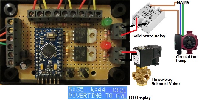
Solar pump controller with diversion valveThis controller is closely based around our standard 2014 Solar Water Heating Pump Controller with LCD Display, but with the addition of a third sensor to measure the temperature of the cylinder (since we only want to send water from the solar panel to the cylinder if the solar water is hot enough to heat it up).

LCD display for solar water heating pump controller with diversion

If/when the temperature measured of the hot tub reaches or exceeds the user’s desired maximum for comfort, a three-way solenoid valve is energised automatically diverting the hot water from the solar panel to the cylinder . The pump then carries on pumping until either the hot tub’s temperature has fallen by a couple of degrees, or the solar panel cools to close to the cylinder temperature.

All sensors used are waterproof digital temperature sensors, and the display is enables the temperature of all three monitors to be constantly monitored. A solid state relay is used to switch the mains powered circulation pump on and off.

If you need a solar water heating pump controller, please take a look at the selection of units we have in the REUK Shop. If you do not find exactly what you need, please email neil@reuk.co.uk with details of your requirements.

Solar Pump Controller with Additional Sensors

Pictured below is a modified version of our standard 2014 Solar Water Heating Pump Controller with LCD.

2014 REUK Solar Water Heating Pump Controller with two extra temperature sensorsIn addition to the standard digital temperature sensors for the solar water heating panel and the hot water tank, this version adds a third sensor to measure ambient air temperature, and a fourth to measure the temperature of the top of the hot water tank.

LCD Display from REUK Solar Water Heating Pump Controller with two extra sensorsThe LCD display has been modified to show the solar and hot water tank temperatures for five seconds, and then the ambient air temperature and top of tank temperatures for five seconds. The bottom line of the display still displays system status and settings information to the user.

If you need a bespoke solar water heating pump controller, please email details of your requirements to neil@reuk.co.uk.

Solar Pump Controller with Timer Override

In our blog post Solar Water Heating Pump Controller with LCD we showed a controller which incorporated a timer override so that the user could force the pump of their solar water heating controller to run at certain times of day or night – for example in the winter to protect against frost, or for any other reason.

This has proved to be quite a popular added feature, so we can now also offer it on request to our 2014 Solar Water Heating Pump Controller with LCD.

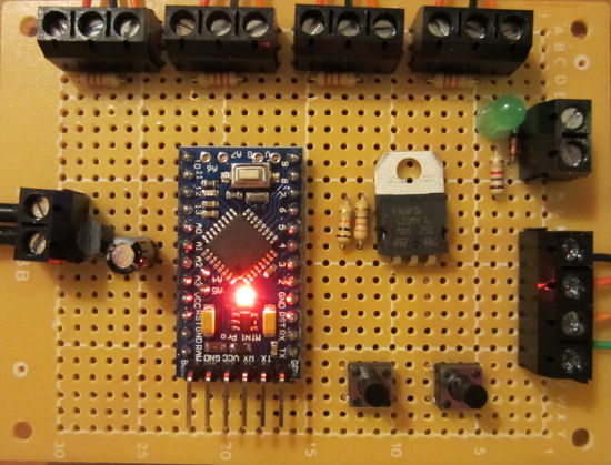
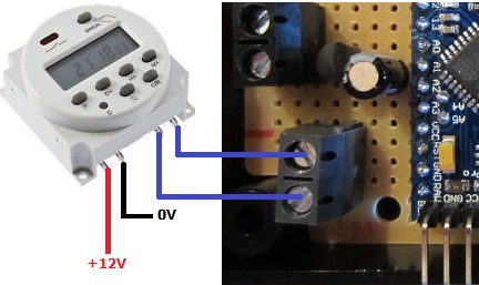
Override solar water heating pump controller with a digital programmable timerThe controller works exactly per the standard 2014 controller, just with a pair of added screw in terminals to which a manual switch or suitable programmable timer switch can be connected for more control.

If you require a solar water heating pump controller with this added feature, please email neil@reuk.co.uk with details of your requirements.

Size Comparison of Pyboard with Raspberry Pi and Arduino UNO

We have just received our Pyboard – a prototyping platform that runs Micropython which is an implementation of the popular Python programming lanuage.

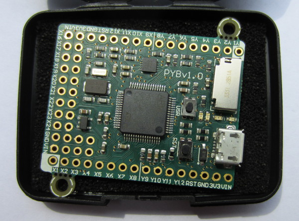
Micropython PyboardAbove is the Pyboard in the hard shell padded case in which it arrived. It looks to be very well made, sturdy, and best of all, physically very small.

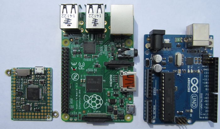
Size comparison between Pyboard, Raspberry Pi B+ and Arduino UNOThe photo above shows just how small the Pyboard is in comparison with the Raspberry Pi Model B+, and an Arduino UNO.

We have lots of projects in the pipeline for which we would previously have used a Raspberry Pi, but the simplicity, size, and much lower power consumption of the Pyboard will often make it the obvious option.

Nabduino Remote Access Board

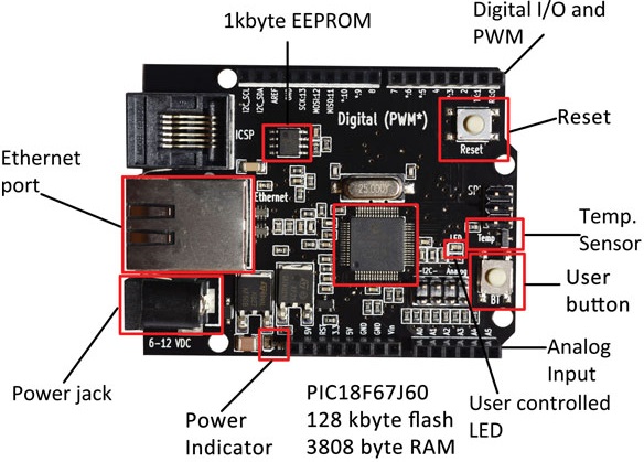
Pictured below is Nabduino – an “open source peer-to-peer remote access embedded board with a user modifiable web-interface developed by Nabto“.

Nabduino board

This small board (available to purchase here: buy Nabduino) can be accessed via a direct encrypted connection through a firewall without the need to change the firewall settings of your router.

If for example you set up a server on a Raspberry Pi – that server will only be visible on your local network unless you change settings on your router to make it visible world wide. If your that server is not set up correctly, then your whole network is at risk – therefore this is best left to experts. Having set up that server, you then need either a static IP address (not usually free of charge) or set up some web services (sometimes free, sometimes not), so that you can find your server when you are outside the local network.

The Nabduino board makes things a lot easier and safer than all that trouble. You simply connect an ethernet cable connected to your local network to the board, connect power to the board, and that is it. Each Nabduino board has a unique ID, and there is a simple web interface which gives you access to the board and its sensors etc accessible from anywhere in the world at XXXX.nabduino.net where XXXX is the ID of your board.

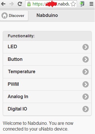
web interface for nabduino board

Via the simple web interface (pictured above), the state of the on board button can be viewed, an on board LED can be controlled, the temperature of the microprocessor can be monitored, five PWM outputs can be set with values from 0-255 for dimming lights or motor control, the status of six analog inputs can be viewed, and thirteen digital pins can be set to input or output and be controlled remotely.

As it stands, Nabduino could be used for simple remote control of a home via relays connected to digital outputs – for example, turning on some lights when you are away from home using your mobile phone or PC. Similarly, very basic home monitoring could be achieved with sensor switches connected to digital inputs. However, much more powerful things can be achieved connecting the Nabduino to an Arduino board so that the Arduino can respond to digital and PWM signals from the Nabduino and carry out any complex logic.

We will be looking at the Nabduino board in much more detail soon. Until then, click here to find out more about Nabto.com.