Solar Water Heating Pump Controller with SD Card Datalogger

Pictured below is a controller we recently made for a solar water heating system including a full datalogger.

solar water heating pump controller with sd card datalogger

This controller is based closely around our 2016 Solar Water Heating Pump Controller which already has basic datalogging functionality – minimum, maximum, and average temperature sensor readings displayed on the LCD.

To this we have added a micro SD card reader and a high accuracy DS3231 Real Time Clock (RTC). Every 15 seconds, the temperature of each of the sensors, the status of the controller, and the date and time are appended to a logging text file on the micro SD card.

arduino data log file from sd cardThe collected data can then be copied over from the SD card to a computer for detailed analysis, graph plotting, and so on.

This controller is based around an Arduino Pro Mini coupled with an LCD module, DS3231 RTC module, micro SD card module, and DS18B20 temperature sensors – all of which are readily available and economically priced. The only difficulties with this project came from the limitations of having only 32KB of flash memory (program space) on the Arduino Pro Mini – not a lot when including so many code libraries for the various modules and sensors as well as 750 lines of of project specific code for this complex datalogging controller.

running out of sram arduino

If you need any kind of datalogger, please email neil@reuk.co.uk with details of your exact requirements.

Hen House Door Controller with Voltage Indication

Pictured below is another of our hen house door controllers – this time using a light detector to automatically detect dawn and dusk (user light level calibration), but with the addition of three battery voltage indicator LEDs.

Hen house door controller with low voltage indicationThis device will open and close a hen house door at dawn and dusk respectively when the measured ambient light level dictates. As this device is to be used with a small 12V battery, there is a chance that the battery will go low on charge preventing reliable operation.

Therefore we have added three LEDs (LED-1, LED-2 and LED-3) connected to flying leads so that they can be located somewhere easily visible while the controller itself is in an enclosure to keep it clean and dry.

When the battery voltage is measured to be greater than 12V, all three LEDs are turned on. When the voltage is between 11.8V and 12V, two are on. When the voltage is between 11.5 and 11.8V, 1 LED is on, and when the voltage is below 11.5V, no LEDs are on.

Each day when the user goes into the hen house to collect eggs, they have a quick visual indication of the state of the battery voltage so that they know when they need to think about recharging it.

If you need a hen house door controller, please email neil@reuk.co.uk with details of any specific requirements you may have.

Picaxe Based Dual One Shot Timer Relay with Code

Pictured below is a simple timer relay circuit we recently made which we will detail here together with the source code for the microcontroller since we have had many requests for example code for timers of this type.

Two option one shot timer relay circuit - PICAXEWe received a request for a timer with two buttons. Pressing the first button was to cause a relay to close for 10 minutes, and pressing the second button was to cause the relay to close for 30 minutes. The relay was to be used to switch a mains powered appliance.

In our article Make a PICAXE Repeating Timer, we show how to make a repeating on/off timer using a PICAXE microcontroller. The timer pictured above differs in that it has button inputs to deal with and also a one-shot instead of repeating timer.

The red LED is used to show which timer is running – off, but flickering on briefly once per second is the 10 minute timer; on, but flickering off briefly once per second is the 30 minute timer. The green LED is connected across the coil of the relay (with a current limiting resistor) to show when the relay is closed.

The PICAXE code below could be greatly reduced in length but to keep it simple to read through, understand, and adapt, we have left it with separate functions for the 10 minute and the 30 minute timers (instead of making one general function which could run for any duration in response to any button press).

symbol button1 = pinC.1
symbol button2 = pinC.2
symbol led = C.0
symbol relay = C.4

' Start with the relay open and the red LED turned off.
low relay
low led

main:
   if button1 = 1 then goto run10minutes
   if button2 = 1 then goto run30minutes
   pause 100
   goto main

run10minutes:
   'make sure button is held a little before closing the relay,
   high led
   for b0 = 1 to 5
      delay 50
      if button1 = 0 then 
         low led
         goto main
      endif
   next b0

   'Close the the relay
   high relay 

   'wait for the button to be released.
   do
      pause 50
   loop while button1 = 1

   low led

   for b0 = 1 to 10 'minutes
      for b1 = 1 to 60 'seconds
         high led
         pause 100
         low led
         pause 900
      next b1
   next b0

   'Open the relay.
   low relay

   goto main

run30minutes:
   'make sure button is held a little before closing the relay,
   high led
   for b0 = 1 to 5
      delay 50
      if button2 = 0 then 
         low led
         goto main
      endif
   next b0

   'Close the the relay
   high relay 

   'wait for the button to be released.
   do
      pause 50
   loop while button2 = 1

   low led

   for b0 = 1 to 30 'minutes
      for b1 = 1 to 60 'seconds
         high led
         pause 900
         low led
         pause 100
      next b1
   next b0

   'Open the relay.
   low relay

   goto main


Battery mAh Capactity Tester

low voltage disconnect with stopwatch for battery testingPictured above is a device we made recently to help estimate the capacity of 12V and 24V batteries. It is based loosely around our 12V Low Voltage Disconnect with Display, but with some major changes and functionality additions.

The customer for this device has a Farnell Electronic load which is capable of discharging batteries at up to 1.5kW (e.g. 12V @ 125A). He wanted to be able to use this to discharge batteries under test, to time accurately the discharge duration, and to automatically turn off the electronic load when the battery voltage falls below a user set level (for example 9.5V for a 12V battery).

This electronic load can be controlled externally by terminals on the back of the unit (Load Enable/Disable). If 5 VDC is connected across those terminals, the electronic load is enabled (turned on), otherwise it is disabled (turned off).

We therefore designed a device which the user can set with their choice of low voltage threshold. Then, when they press the Start Button, a regulated 5V is put across the terminals on the back of the electronic load which starts discharging the battery under test. At the same time, a stopwatch (created in software on the Arduino Pro Mini around which this controller is built) starts to display the number of days, hours, minutes, and seconds that have elapsed since the battery discharge began.

When the battery voltage is measured to have fallen below the low voltage threshold, the stopwatch stops, and the 5V signal to the electronic load is disconnected preventing the battery being discharged any further and potentially being permanently damaged.

The time on the stopwatch is saved in memory on our device and is displayed on the LCD until the user presses the reset button. It is saved in this way just in case after a multi-hour/day test has been completed, someone accidentally disconnects the battery from the timing device before noting the displayed timing results.

Pictured below is an alternative version of the same thing, designed for use with 12V batteries, and provided with an OLED display on board.

Device to time discharge of 12V battery to calculate mah capacity

This device works the same as the unit detailed above, but it has a smaller footprint, draws slightly less current from the battery itself, and it has a 1 Amp rated output to the electronic load @ 12VDC.

OLED display on battery mah capacity meter device

Pictured above is the display in standard operation showing the battery voltage at present, the low voltage threshold level (below which the electronic load will be switched off), and the running time so far.

Below shows the display when the device is in programming mode when the low voltage threshold can be set to a suitable value by the user.battery mah capacity meter low voltage disconnect

If you need any kind of voltage measuring device, low voltage disconnect, and/or timer, please email neil@reuk.co.uk with details of your exact requirements.

Automatic Irrigation System Timer Controller

Pictured below is a timer controller we recently made for a commercial irrigation system. This set up currently has four solenoid valves which when opened, water different regions in a large greenhouse. The number of solenoid valves will soon be increased to eight, so we had to make this controller work now with four valves, but be ready to control eight in the future. The controller is based around an Arduino Pro Mini.

automatic irrigation timer controller

The main controller board above drives four or eight of the 10 Amp rated relays on the relay board pictured below.relay board for irrigation timer controller

The small button at the top left of the main controller board can be used to toggle between four valve or eight valve operation as per the user’s requirements.

The valves are to be opened on a four hour cycle. With four valves, each valve is opened for 15 minutes in turn with a 15 minute delay between. Then after a two hour delay, the cycle repeats. With eight valves, each valve is opened in turn for 15 minutes with a 15 minute delay between each. The cycle then immediately repeats.

If you need an automatic timer controller for an irrigation system, please email neil@reuk.co.uk with details of your exact requirements.

Window Blind Motor Timer Controller

Pictured below is a device we made recently to control window blinds so that they automatically close in the evening and open in the morning to give the impression that someone is at home when they are away on holiday.Window blind motor timer controllerThe motor set up with these particular blinds is a small 3 Volt DC unit, but the controller is powered by 12 Volt DC. The motor needs to be turned forwards to open the blinds and turn in reverse to close the blinds. Therefore a pair of relays are used (as explained here: Reversing the Polarity of a Motor with Two Relays) to give the reversing polarity output for the motor.

A programming button is fitted to the device which is used to set the number of seconds that the motor is to run to fully open or fully close the blinds. In addition, there are a pair of microswitches which act as limit switches ensuring that if blinds reach the end of their motion before the expected time, the motor will be turned off so that it does not burn out under the heavy load of fighting resistance. Therefore, the motor runs until either the user programmed run time has elapsed or the limit switch is hit. If there was not a time limit, then if the blinds became jammed, the limit switch would never be reached, and again there would be the risk of the motor burning out.

If you need any type of motor controller or timer, please email neil@reuk.co.uk with details of your exact requirements.

Motion Sensing MP3 Player for Bird Hide

Pictured below is a device we recently made for use within a bird hide. When motion is detected inside the hide (via a small KC7783R PIR sensor module), a small MP3 player is turned on to play an educational soundtrack.

automatic motion detecting MP3 player for educational bird hideBecause the length of the track may be changed, the device is fitted with a button which enables the number of minutes that the MP3 player is powered after motion detection to be adjusted so that the whole track is played, but no power is wasted by not leaving the MP3 powered when the track has played (since this is a solar PV powered set up).

If you need any type of motion sensing device or timer, please email neil@reuk.co.uk with details of your requirements.

Archery Timing Circuit

timing circuit for competitive archery trainingPictured above is a timing circuit for archery competitions. Outdoor archers shoot six arrows in one go and are allowed 4 minutes. Indoor archers shoot three arrows in one go and are allowed 2 minutes.

The user can select one of two options – option 1 (outdoor) and option 2 (indoor) for either a two minute or four minute competition. The controller board itself has a red, yellow, and green LED on it and a small buzzer. There are also four relays which can control larger lights – e.g. when the red LED is illuminates, a relay will be closed which can control multiple large red lights. The same is repeated for each LED and also for the buzzer relay which can control multiple buzzers or sirens.

The Mode button is used to select the desired timing option. The red LED will be on while the controller is sleeping. When the Start/Stop button is pressed, the timer starts and the green LED turns on. With the outdoor timing option, the green LED stays on for 3 minutes and 30 seconds. With the indoor timing option, the green LED stays on for 1 minute and 30 seconds. Then the yellow LED turns on to give the archer notice that their time is running out. After 30 seconds the red LED turns back on again and the buzzer sounds briefly to indicate that time is up, and the device is reset ready for the next archer.

While the timer is running, you can press the Start/Stop button to cancel the timer and reset the controller. Alternatively, you can press the Pause button to pause the competition. The buzzer sounds 3 times quickly to indicate that the competition has been paused and then when the Pause button is pressed again, the buzzer sounds 3 times. The timer continues from where it left off exactly after the buzzer sounds for the third time.

If you need any kind of bespoke timer device, email neil@reuk.co.uk with details of your exact requirements.

Saving Arduino Collected Data to Text File on Windows

We are often asked how to log data from an Arduino to a text file saved on a Windows PC. This is very simple with Linux and Mac OS, but it can be also be achieved on Windows with minimal effort.

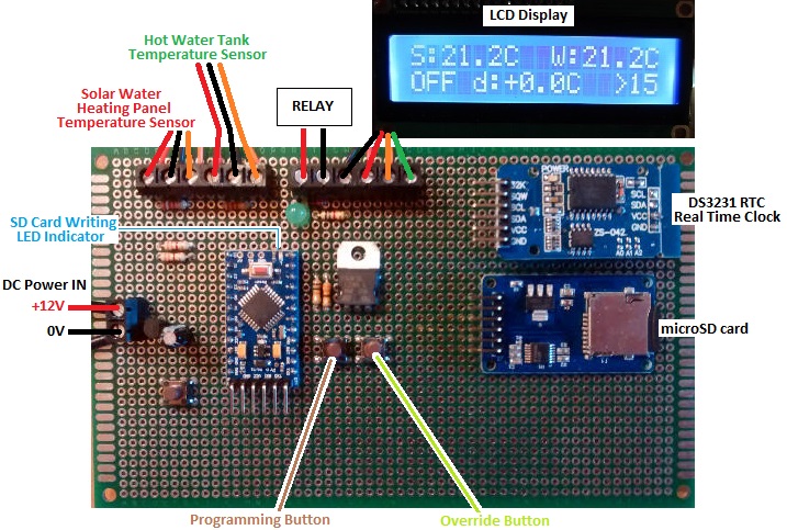
We make a lot of dataloggers, the majority of which either store data internally and then output a summary to an LCD display, or dump all collected data to an SD card for later processing and analysis on a PC. However, it is relatively simple to collect data from any number of sensors connected to an Arduino board and send that data over a serial connection directly to a text file on a PC.

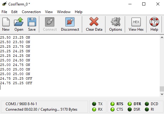
There are many software options available, but we typically use CoolTerm (available free of charge here: download CoolTerm) which is a serial monitor which will also capture transmitted data to a text file and automatically add time stamps to each line of data which are essential for a good datalogger.

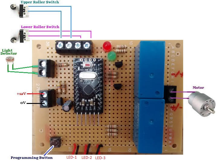
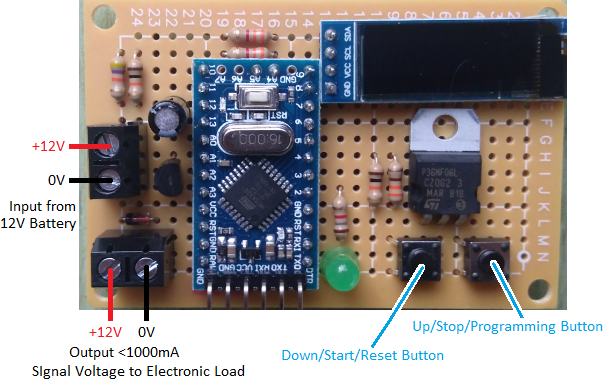
As an example we slightly modified the code for our 2016 solar water heating pump controller so that every time data is taken from the two connected digital temperature sensors, those measurements and also the system status (pump ON or OFF) are output through the serial port to a connected PC. (Full details on generating Serial output from an Arduino are available here: Arduino Serial from the official Arduino Reference site.)

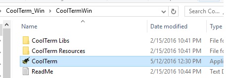
Download CoolTerm from the link already provided above. You will end up with an approximately 10MB zip file which needs to be extracted. When that is done, go into the folder created, and double click on the CoolTerm application.

Launch CoolTerm application
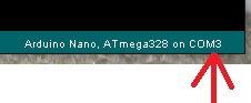
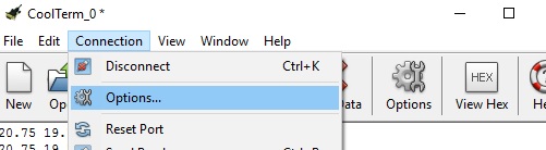
Click on Connection > Options and then in Serial Port Options select the Port you would like to use. If you are using the Arduino IDE, in the bottom right hand corner of the window will be shown the type of board you are using followed by COM# where # is the number of the port your Arduino is currently set up to use and is also the port you should select within CoolTerm).

Selecting the serial COM port to use with CoolTerm with ArduinoAt the same time set the baudrate to 9600 (making sure that in the sketch you have uploaded to your Arduino, you have also included Serial.begin(9600); in the setup() function.

CoolTerm connection options

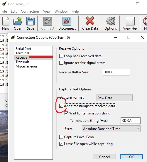
Assuming that you would like all data to be timestamped (adding the date and time to every line of data sent), do Connection > Options > Receive and check the ‘Add timestamps to received data’ box.

timestamp serial data from Arduino and store in text file on PC

Then to have any serial data from your Arduino automatically stored in a text file on the PC, do Connection > Capture to Text File and then click on Start. You then just have to set the name for the file that you would like your data to be stored in, and your datalogger is complete.

arduino coolterm serial monitor showing arduino collected data

To stop collecting data, you can either click on the large Disconnect icon, or if you want to stay connected to the Arduino board, do Connection > Capture to Text File > Stop.

Once you have either disconnected the Arduino board or Stopped the capture, you cannot then restart and append data to the same file – you can only overwrite the original file or start a new one. If you want to pause capture and then restart it to append to the same file, do Connection > Capture to Text File > Pause to pause, and then Connection > Capture to Text File > Resume to resume it at a later time.

Data collected from solar pump controller from Arduino via Serial and CoolTerm to PC

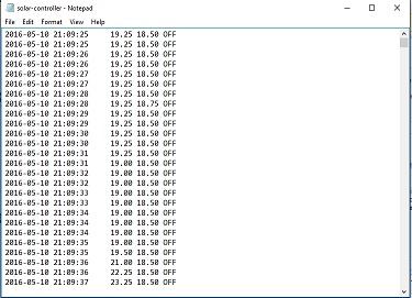
When you have finished capturing data, you will end up with a text file of everything captured which can be processed and visualised using Excel or a similar application.
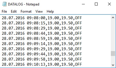
Pistol Shooting Training Timer

Competitive pistol shooting trainer timerPictured above is a timer we recently made for use in competitive pistol shooting training. There is a microswitch under a flat plate on which the pistol lies. When the shooter picks up the pistol, the timer starts counting down a user set value of either 6, 8, or 10 seconds after which a buzzer sounds briefly telling the shooter to replace the pistol. The duration of the timer is set using a button to step through the three possible options, with an LED (red, yellow, or green) illuminated to show the currently selection option. This will all be fitted inside an enclosure with the microswitch connected through the circuit board, and the LEDs and timer mode selection button mounted in the lid of the enclosure.

This timer is built around an Arduino Pro Mini board and uses its internal clock for timings as it is accurate enough over such short timing intervals (+/-1 millisecond or better over 10 seconds) when considered in conjunction with the time it takes the microswitch to open/close, or sound to actually start to emit from a buzzer when it is first powered.

If you need any kind of special timer, please email neil@reuk.co.uk with details of your specific requirements.