Heating Circuit Pump Controller

Pictured below is a controller we recently made for a wood fire cooker based heating circuit.
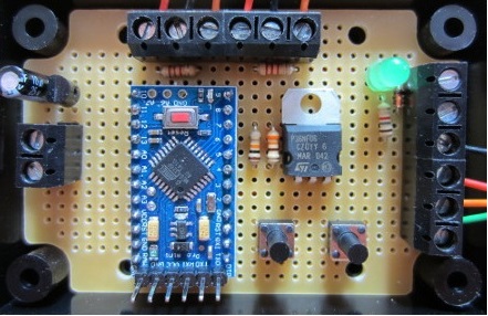
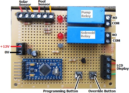
heating circuit pump controllerThe controller itself is physically identical to our standard 2014 Solar Water Heating Pump controller with an LCD to display temperatures and system status and a couple of ds18b20 digital temperature sensors. However, it has been completely re-programmed for an alternative use.

The customer has an Esse wood fired cooker with a 2.5kW domestic water circuit. This thermosyphon water heating circuit feeds a 140 litre thermal store in which a heat exchanger is used to heat up domestic hot water.

As there is some surplus heat over domestic hot water requirements, a pump is required to divert surplus heat to a panel radiator situated below the tank.

Two temperature sensors are to be fitted – one in the middle of the storage tank and the other on the return thermosyphon flow to the cooker.

The controller we put together for this system measures the temperature of the two sensors, and if both are found to be above user set values (for example, 80C for the tank and 45°C for the return flow), then the pump will be turned on to divert hot water to the radiator. When either of the two sensor temperature subsequently drops 2°C or more below the set values, the pump will be turned off sending hot water back into the storage tank.

If you need any type of water heating system controller, email neil@reuk.co.uk with details of your exact requirements.
Voltage Measuring Datalogger with micro SD Card

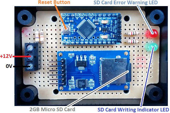
Pictured below is an Arduino-based datalogger we recently made for measuring the voltage output of induced EMF in coils through which a magnet is passing. The voltage output needs to be logged once per second for up to a few hours.

SD card dataloggerThis particular datalogger is 12VDC powered, and will measure and log voltages up to 15VDC. (The induced voltage to be measured in this project has been measured with an oscilloscope not to exceed 5V).

Each time the datalogger is connected to the power source and to the coil to be measured, a new log file is created on the supplied 2GB micro-SD card. An on board reset button can also be used to start a new log file.

On start up or when reset, the SD card is initialised and checked to ensure that it is present and working properly. If it is not, the red LED turns on and stays on to warn the user – there are few things worse than running an experiment only to find that no data was collected. If all is well with the SD card, then once every second the coil voltage is measured and appended to the latest log file.

When the experiments are complete, the SD card can be removed from the datalogger and accessed via a PC for processing and analysis. The generated datalog files are simple text files with each measured data point on a new line in chronological order.

If you need a datalogger,  email details of your exact requirements to neil@reuk.co.uk.

Automatic Plant Propagator Thermostat

Pictured below is a thermostat we recently made to maintain the temperature in a plant propagator fitted with 12V heat pads.

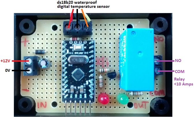
Automatic compost heat pad relay thermostatThe propagator is located in a potting shed with two lead acid batteries charged a 40W PV solar panel with a solar charge controller. Our thermostat includes a waterproof stainless steel encased DS18B20 digital temperature sensor which is to be buried in the moist compost in the propagator. When the measured temperature falls below 17 degrees Celcius, the heating pads are turned on via the on board 10A rated relay, and then remain on until the temperature of the compost reaches 23 degrees Celcius.

Normally for these types of simple thermostat we use a PICAXE microcontroller, but we chose instead to use an Arduino Pro Mini as this meant that we did not have to deal with processing negative temperatures programmatically. (PICAXE only has integer mathematics, so cannot easily deal with fractions of numbers or negative numbers. If the propagator is not used for a while during the winter, below zero temperature could be measured as it is located outdoors.)

If you need any kind of bespoke thermostatic controller, email neil@reuk.co.uk with details of your requirements.

(See here: http://www.reuk.co.uk/wordpress/programmable-automatic-plant-propagator-thermostat/ for a user programmable version of this device for which different temperature ranges can be set.)

Solar Water Heating Pump Controller with Maximum Pump Run Time

Our 2014 Solar Water Heating Pump Controller with LCD is one of our best selling products. We recently receive an original request for a modified version of this controller for use with a solar heated swimming pool in France. This particular system has a 12V powered submersible pump which has a maximum duty cycle of 15 minutes – i.e. if the pump is run for longer than 15 minutes continuously it could be damaged.

In general the pump in such a system will not run for that long, but it is likely to happen from time to time – particularly in the spring when the pool is cool, but the panel is getting well heated in the middle of the day. Therefore something needs to be added to the controller to protect it from this eventuality. Also, this controller has a manual override to force the pump to run, and this could be forgotten and left on for hours burning out a vulnerable pump if there is no protection.

solar water heating pump controller with maximum pump run time

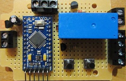
Pictured above is controller board we made – this time with a relay to switch the current to the pump rather than the standard MOSFET 2A 12V output. We also added waterproof temperature sensors to make the device suitable for pool use.

To the standard user programming options we added the ability to set the maximum number of minutes the pump may run continuously, and the number of minutes the pump must then be left off before it can be turned on again. These values can be set to anything from 1-60 minutes each to give flexibility should the pump need to be changed in the future. The user of this controller intends to set a 12 minute maximum run time and a 3 minute forced off time. (As the 2014 controller is Arduino based, we used the millis() function to keep track of time while the pump is running).

If you need any kind of solar water heating pump controller, please email details of your exact requirements to neil@reuk.co.uk.

Poultry Lighting Controller with LVD and Display

We have been selling a selection of poultry lighting controllers for many years now – devices designed to stimulate egg production in the winter months using artificial light at dusk and/or before dawn to trick the birds.

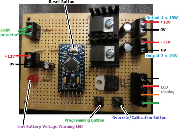
Pictured below is a bespoke lighting controller we recently made for a more advanced poultry lighting controller including a double voltage regulator so that more LED bulbs can be used in a large poultry house, an automatic low voltage disconnect, and an LCD display to show system status and for use in setting up the system.

Poultry lighting controller with low voltage disconnect and display

This device will automatically detect dusk and turn on the lights in the poultry house for a user-programmable number of hours (including zero). The lights then turn off (if they had been on) and remain off for 9 hours to give the birds a 9 hour sleep and a 15 hour day for maximum egg production. The lights then turn on in the early morning and remain on until dawn when natural light is bright enough to take over.

display for poultry lighting controller with lvd

Dawn and dusk are detected using a light dependent resistor, and the user can calibrate the exact light level which they consider to be at the threshold between day and dusk, and between night and dawn.

To protect the battery from being run too low of charge and being damaged, the user can programme into the device three trigger voltages: a voltage below which the on board red LED will turn on as an early warning, a voltage below which the output (to the lights if on) will be turned off, and a voltage above which the low voltage disconnect will be cancelled restoring the outputs automatically when the battery is recharged.

manual override active on poultry lighting controller

There is also a manual override option which enables the lights to be turned on manually at any time (low voltage disconnect permitting) when the poultry house needs to be cleaned or the eggs to be collected etc.

At all times the backlit LCD display shows the status of the system including the currently measured battery voltage, whether the LVD is engaged, whether the outputs are on or off, the current position in the cycle DAY, DUSK, SLEEP, PREDAWN, DAWN (or MANUAL when the override is active), and the currently measured light level relative to the user set threshold.

If you need any kind of poultry lighting solution, please email neil@reuk.co.uk with details of your exact requirements and we should be able to put something suitable together for you.

Solar Pool Pump Controller with Overheat Diversion

Pictured below is a controller we recently made based around our standard 2014 Solar Pump Controller. The modifications and additions have been made so that this device can be used to safely control the pump for a small solar heated pool located in sunny Egypt, ensuring that neither the pool nor the solar panel will overheat in the extreme weather conditions found there.

Solar water heating pump controller with automatic diversion overheat protectionWith our standard controller, the pool temperature could become unpleasantly or dangerously hot in very sunny climates. We have made many controllers which automatically turn off the pump if the pool temperature exceeds a user set threshold (such as this simple solar hot tub pump controller). However, just turning off the pump in the middle of summer in Egypt could easily result in the the contents of the solar collector boiling which could also be dangerous and damaging.

Therefore this particular controller can be set up by the user (via the on board buttons and provided LCD display) with a maximum pool temperature. If the pump is running (because the solar collector is hot) and the pool reaches the maximum temperature, a relay closes which turn energises a solenoid valve. This valve will divert the solar heated water away from the pool and through a copper coil into a vented tank or barrel where it can boil/evaporate off safely. A float valve at the top of this container will top it up with cool water to replace evaporative losses. When the pool temperature falls by two degrees, the solenoid valve will be de-energised and the solar heating of the pool will start again.

If you need any kind of solar water heating pump controller, have a look at our range of off the shelf products here: Solar Water Heating, and if you cannot find something suitable, email neil@reuk.co.uk with details of your exact requirements so that we can design and build you something.

Real Time Clock Timebase for Lazy Clock

Pictured below is a timer we recently designed and built to act as an accurate timebase for a Lazy Clock (see here for details: Lazy Clock – PDF plans for this wood gear clock driven by a solenoid)

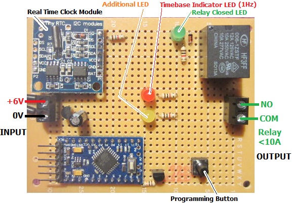
Real Time Clock with relay output for timebase of Lazy ClockThe device we made has a real time clock module based around the Dallas DS1307 Real Time Clock (RTC) – top left of the board pictured above. This can be set up (via the Arduino Pro Mini at the bottom left of the board) to output a 1Hz square wave – i.e. outputting a high signal for exactly 0.5 seconds followed by a low signal for exactly 0.5 seconds, repeating.

The device can be programmed by the user to close the on board relay for 0.25, 0.50, or 0.75 seconds, every 1, 2, 3, 4, 5..etc seconds using this 1Hz square wave as a trigger. The relay switches the solenoid which in turn keeps the Lazy Clock accurate to within a few seconds per day.

If you need any kind of relay timer, please email neil@reuk.co.uk with details of your exact requirements.
Modified Solar Pump Controller for Solar Air Heating

Pictured below is a custom controller we recently made based around our 2014 Solar Water Heating Pump Controller with LCD.

Modified-2014-controller

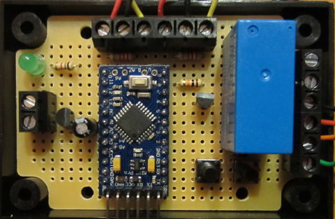
This device is designed to be used with a solar air heating system. There is one waterproof temperature sensor to detect the temperature within the solar air heating panel, with the second sensor mounted directly to the circuit board to measure ambient internal temperature.

Instead of the usual 1 Amp rated output for connection to a relay, this board has a relay fitted directly to it to directly switch the power to a 250 cfm fan which drives hot air from the solar collector into the house.

As with the standard 2014 solar pump controller, this device has an LCD display to show the temperature of the solar collector and (in this case) the ambient air temperature and system status information, as well as enabling temperature differentials to be set at which the fan will be turned on and then turned off and to control a manual override.

If you need a controller similar to this, please email neil@reuk.co.uk with details of your exact requirements.
East West Solar Water Heating Pump Controller

We have recently finished work on a new solar water heating pump controller to be used where the array of solar water heating panels is split between an East and a West facing roof instead of the more typical single South-facing (in the Northern Hemisphere) solar array. This controller has been based around our 2014 Solar Water Heating Pump Controller with Display with some additions and changes.

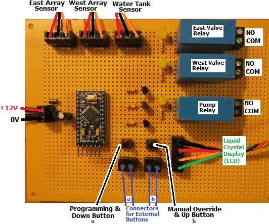
Solar water heating pump controller for use with an East / West solar arrayThis controller has connections for three waterproof digital temperature sensors – one for the East array, one for the West array, and one for the hot water tank (or pool).

The customer for this controller did not want to have the water flowing through both solar arrays at the same time to prevent heat collected on the hotter sunny side of the roof from being immediately radiated away from the cooler side. Therefore his system features two solenoid water valves which, when the pump is turned on, will ensure that water only flows through the hotter of the two solar heating arrays.

Display for East / West solar water heating pump controller

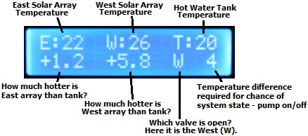
The display (LCD) for this controller shows the three measured temperatures on the top line, the temperature difference between each solar array and the hot water tank (or pool), which if either of the valves is open (therefore also indicating that the pump is running), and the temperature difference (diffON or diffOFF) required for the system to change state (i.e. for the pump to turn on or off).

In the above photograph, the valve on the West side is open, and the west solar array is +5.8 degrees Celcius hotter than the hot water tank. When this temperature difference falls below 4 degrees (diffOFF), as the East array is relatively cool (just +1.2 degees hotter than the tank) the West valve will close, the pump will turn off, and the display will now show diffON – the temperature difference required before the pump can be turned on again. (If the East array had been hotter than the tank by more than diffON at this time then the pump would keep going, the East valve would open and the West valve would close).

This controller also has a manual override facility which lets the user force the pump to run with the East valve open, the West valve open, or even both valves open at the same time – for example while testing. The values of diffON and diffOFF can be set by the user as per the standard 2014 solar water heating pump controller.

If you need a controller like this (or any other solar water heating pump controller), please email neil@reuk.co.uk with details of your exact requirements.

Thermostat with Datalogger and LCD Display

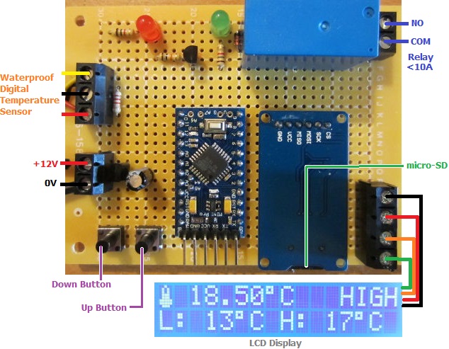
Pictured below is a thermostat we have just completed which includes an LCD display and temperature datalogging to a micro-SD card.

Cooling thermostat with LCD display and SC card dataloggerThis will be used to control and monitor a small (4′ x 4′ x 6′) shed cooling system. The cooling parts of a second hand fridge have been mounted to an inside wall of the shed, and this thermostat with its digital temperature sensor and relay is used to turn the cooler on and off as and when required to keep the shed cool.

The display shows the current temperature of the shed and the system status. The user can set the high temperature and low temperature thresholds at which the cooler will be turned on and off respectively; and their chosen thresholds are displayed on the bottom line of the display.

Every 30 seconds the temperature of the sensor and the cooler status (on=1, off=0) are logged (written to a csv text file on a micro-SD card) for later analysis on a computer using Excel or similar.

If you need something similar to this, or anything else utilising temperature datalogging, monitoring, and control, email neil@reuk.co.uk with details of your requirements.