We have been doing a lot more work with Raspberry Pi over the last few months on some interesting projects which we will soon be covering on the REUK.co.uk website.
Raspberry Pi has an infinite number of uses and offers a great mixture of power, flexibility, and price, but it is lacking in one regard – its GPIO (general purpose input output) does not offer analogue input (ADC – analog digital converter) pins. Therefore it cannot be connected directly to non-digital temperature sensors, light detectors, or measure voltages etc. (This is in comparison to the similarly priced Beaglebone Black which offers seven 12-bit ADC pins for analogue inputs, or Arduino.)
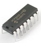 There are however simple and relatively cheap ways around this, one of which we will cover here: the MCP3008 10-bit 8 channel ADC pictured above. This is a microchip which can take up to 8 analogue inputs, and communicate their digital equivalent values (0-1023) to the Raspberry Pi via the SPI serial interface.
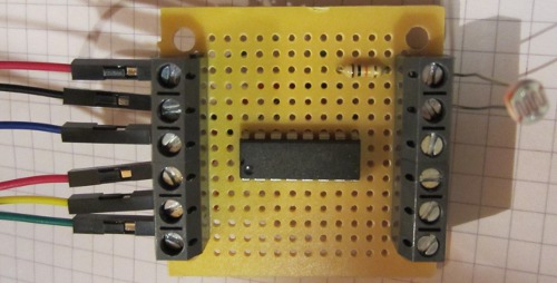
Pictured above is a small board we have made with the MCP3008 at its centre. Coming in on the left side are six connections to the Raspberry Pi GPIO – 3.3V and GND power connections, and the four connections for the SPI interface.

To make the connections to the GPIO we used male to female jumper links. The female end pushes over a GPIO pin, and the male end goes into a screw in terminal on our MCP3008 board.
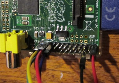
In order to set up the Raspberry Pi to use the SPI interface there are some commands which are required and you also need to install the SpiDev module. This is all detailed together with connection diagrams in the links to some external resources at the end of this post.
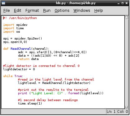
The above shows the simple Python script we used to measure the light level of a light detector connected to our MCP3008 board (making a voltage divider with the light detector and a 10K resistor and feeding the output voltage into channel 0 of the MCP3008 ADC chip. The script simply measures the light level once per second and outputs it to the terminal.
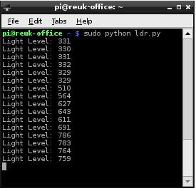 The measured light level is given a digital value from 0-1023. As we wired it, higher values correspond to darker light levels, so the above screen shot shows the results as the light detector was slowly shaded.
Having got the digital value for the analog light level in the Raspberry Pi, you can do anything with it – control lights, detect dawn and dusk, control motorised curtains, log it, view it online and so on. It is also possible to use the exact same technique and MCP3008 to measure a huge range of other analogue signals including temperature sensors, voltage measurement, potentiometers, etc.
Here are links to some useful resources online to find out more information about reading analogue signals with a Raspberry Pi:
Analogue Sensors on the Raspberry Pi Using an MCP3008 – this offers comprehensive details on setting up the Raspberry Pi for SPI as well as connecting it to the MCP3008 and related Python scripts.
Analog Inputs for Raspberry Pi using MCP3008 – a guide from Adafruit.
MCP3008 Datasheet – get a better understanding of the ADC.
