New Product – 12V PIR Motion Sensor Timer

This week we have launched a new product – a timer designed for use with the 12V PIR motion sensors typically found in burglar alarm systems.

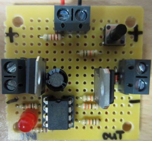
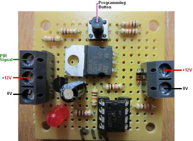
REUK Programmable PIR motion detector timer

This device is based loosely on the PIR Relay Timer we have been selling since 2007 designed to keep an output such as lighting or an alarm on for a user programmable duration after motion has been detected by a PIR sensor.

This new device does not come with a relay; instead with an up to 3 Amp 12VDC output which can be used to directly power to up to 3A of lighting etc, or which can be connected across the coil of the user’s choice of relay – solid state or standard – to switch any current or voltage as required.

The user can programme how long the output will remain on after motion was last detected in steps of 10 seconds – 10, 20, 30, 40…etc seconds as per requirements.

This device is not currently available in the REUK Shop, but is available exclusively here: REUK PIR Timer for now.

Project of the Day – Special Programmable Timer

We had a special request for a modified version of our REUK Super Timer 2 for use setting dosing levels during plant development.

Our super timer can be programmed to close a relay for an interval from 1 second to 99 hours, and then open that relay for from 1 second to 99 hours repeating. It is a very useful and popular product, but in this particular application it was necessary to make the programming of the ON and OFF durations as simple as possible and to also display the current settings so that it was immediately obvious to anyone looking at it what those settings were.

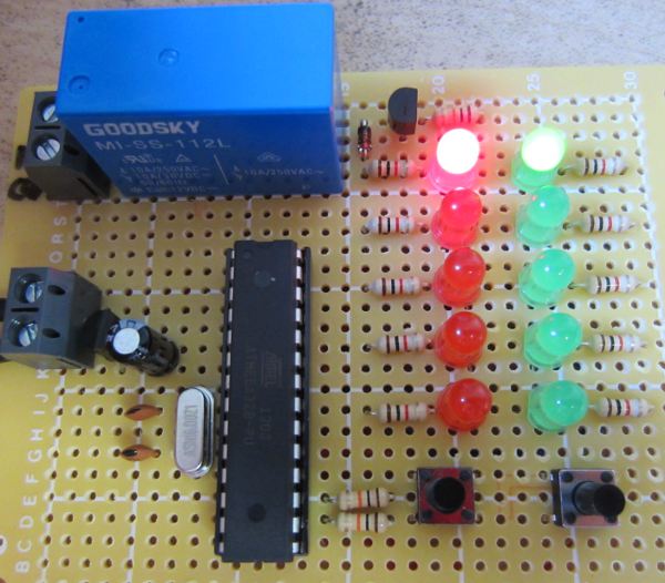
simple relay timer with displayPictured above is our solution to this problem. The possible ON durations required were 1,2,3,4 or 5 seconds, and the OFF durations 1,2,3,4 or 5 minutes. Therefore there are two buttons – one to move through the ON options 1 to 2 to 3…etc seconds, and another button to move through the OFF options 1 to 2 to 3… etc minutes. The green LEDs show which ON option has been chosen, and the red LEDs show which OFF option has been chosen.

Because of the large number of inputs and outputs, 10 LEDs, two buttons, and a relay, we chose to use Arduino for this project, but as a standalone microcontroller as explained here: Standalone Arduino on a Breadboard so that everything could be put tidily on the one circuit board.

Project of the Day – Immersion Controller using Electricity Meter LED

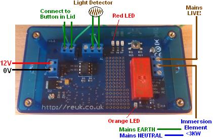
Our standard Surplus PV Immersion Controller uses a light detector to estimate when the solar electricity generation from a domestic PV array is above a user-set threshold. It then turns on an immersion heating element to use the surplus electricity rather than exporting it to the grid.
REUK

This simple light detector approach works particularly well in homes where the householder is out all day since once the baseline electricity needs of the home are met, the surplus electricity can be used for free water heating instead of being exported (which would earn just a few pennies per kWh unit of electricity exported).

However, this system is not a true surplus electricity controller since if the home owner has a 4 kW solar array, and a 3kW immersion element, then if more than 1kW of electricity is being used in the home on other things – e.g. kettle, washing machine, or other heavy loads, electricity will be imported at a cost to cover any shortfall.

This week we have been working on the next level approach which is very useful for some households depending on how their electricity meter(s) are set up. In our article Flashing LED on Electricity Meter we looked at how modern electricity meters are fitted with a red LED which flashes at a rate proportional to the power passing through them. They are marked with something like 1000 Imp/Kwh which means that the LED will flash 1000 times per kWh unit of electricity passing through.

The meter for which we made this modified controller this week has such an LED which flashes while electricity is being exported and is off while importing. The flash rate is 1000 Imp/kWh and so if 1000 Watts of electricity is being exported, the LED will flash once every 3.6 seconds; if 2000 Watts of electricity is being exported, the LED will flash once every 1.8 seconds; if 100 Watts of electricity is being exported, the LED will flash once every 36 seconds, etc.

Using this information we modified the programming on our standard immersion controller so that instead of the light detector measuring the level of solar radiation and therefore estimating the power generated by the solar panel, it now measures the LED flash rate on the electricity meter so that it knows how much electricity is actually being exported net of any loads in the home.

half wave rectification of electricity to halve power use of immersion element

This controller is being used with a 1.5kW immersion heating element which is powered via a diode to give half-wave AC electricity cutting the power of the immersion element in half to 750 Watts. The solar array is rated at 4 kW.

We programmed this particular controller to turn on the immersion element when 1,100 Watts or more is being exported and then turn off the element when 200 Watts or less are being exported. If 1,100 Watts are being exported then when the immersion heating element turns on, the export will instantly fall down to 350 Watts, and there is an extra 150 Watts of hysteresis in place so that the immersion will not be turned off when the power taken by the devices using electricity in the home fluctuates a bit.

If you are interested in this type of modified immersion controller, please email neil@reuk.co.uk with details of your electricity meter(s), immersion power rating, and solar array power rating.
Project of the Day – Power Inverter Fan Thermostat

inverter fan themostat

Today we have been working on a small thermostat controller for the fan in a 24VDC power inverter. The existing fan was too noisy and on constantly, and was replaced with a quiet and more efficient fan to keep the power inverter internals cool with the above thermostat added so that the fan is only powered when necessary.

The temperature sensor used (not pictured) is an LM335.

The user can programme this thermostat to automatically turn on the fan at their choice of temperature, and the fan will then automatically turn off when the temperature has fallen by 5 or more degrees from that level.

New Dawn Dusk Lighting Controller – Cheaper and Smaller

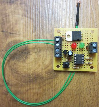
Today we started selling a new stripped-down miniaturised and more economical (almost half the price) version of our standard 12V REUK Super LDR Dawn Dusk Relay Controller. This is a five mode user-calibratable light detector triggered light/dark dawn/dusk relay controller which has  a huge range of possible applications from security lighting, poultry lighting, home automation, and much more.

Mini dawn dusk relay controller

In the new alternative version (pictured above) no relay is supplied. Instead there is a 1 Amp maximum output which can control up to 12 Watts of LED lighting or other low power device(s), or can be connected across the coil of a relay to switch any device of any voltage or current/power requirement.

The modes of operation for this controller are as follows:
Mode 1: Output on when dark
Mode 2: Output on when light
Mode 3: Output on from dusk until dawn
Mode 4: On for X hours (user programmable) after dusk
Mode 5: Off for X hours (user programmable) after dusk and then on until dawn.

This item is now available here in the REUK Shop:

REUK Mini LDR Dusk Dawn Lighting Controller for £13.95.

Project of the Day – Well Pump Float Switch Fail Safe Controller

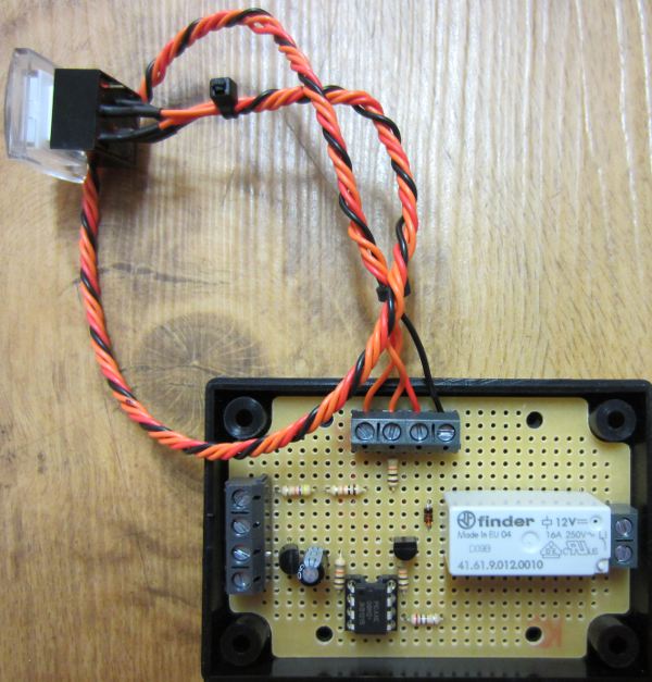
Today we put together a fail safe protection system for a well pump used to fill a header tank for a domestic water supply. This fail safe is designed to be connected in series with the existing pump controlling Stuart Turner float switch to cut the power to the pump if the header tank is about to overflow. If the primary float switch sticks or otherwise fails and does not turn off the pump when it should, the fail safe system will override it and turn off the pump.

The heavy duty MONO pump in this particular system is rated at 1hp (0.73kW) and pumps water up from from a well 15 metres below the header tank at a rate of 10 gallons per minute. Therefore a float switch failure and the subsequent flood of water overflowing the header tank and going through the house could be extremely serious and costly.

fail safe protection for well pumpPictured above is the solution we came up with. A secondary float switch is fitted into the header tank just above the existing float switch. In normal operation, this secondary float switch is closed which keeps a relay on our controller closed through which the mains live passes on its way to the existing primary float switch.

If the level of the water in the header tank reaches the secondary float switch, the float rises up which opens the switch. This causes the relay on our controller to open cutting the live connection to the primary float switch and therefore to the pump keeping it turned off.

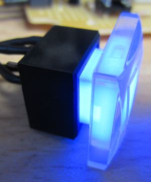
button with integrated LED

We have added a button (pictured above) which under normal operation can be used to test the fail safe for peace of mind – pressing the button causes the relay to open and the LED in the button to light up for a few seconds.

If the fail safe is triggered by high water then the pump turns off and the LED in the button turns on to give a visual warning that something has gone wrong. The home owner must then check the header tank, remove any obstruction from the primary float switch, confirm that float switch is working reliably, and then press the button to manually reset the fail safe. There is no automatic reset of the fail safe as this would be far too risky – flood damage was averted and now manual intervention is a must.

12V Regulator with Low Voltage Disconnect (LVD)

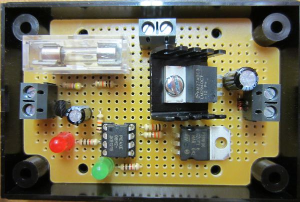
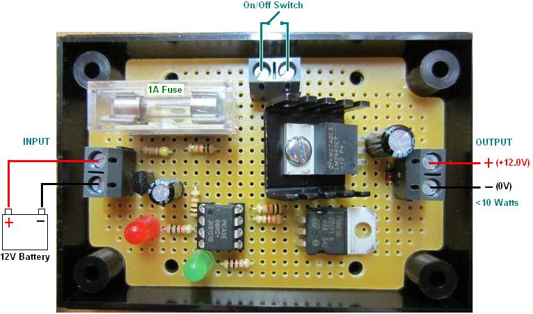
Pictured below is our new 12V regulator with integrated Low Voltage Disconnect (LVD) battery protection for LED lighting applications.

12v low voltage disconnect (LVD) with 12V low dropout regulator outputThis device will supply power to up to 10 Watts of LED lighting at a safe voltage when connected to a 12V battery while at the same time protecting the battery from being excessively discharged and therefore having its lifespan reduced. It is a combination of our established 12V regulator and low voltage disconnect technologies.

Connections for 12V regulator with low voltage disconnect - REUK

We currently only have this item for sale here: 12V regulator with LVD, but we will be adding it to the REUK Shop soon.

Solar Water Heating Pump Controller with Solid State Relay

A few days ago (link to the article) we described our new solar water heating pump controller based around our standard 2013 controller, but fitted with waterproof digital temperature sensors for use in pools, hot-tubs, and so on.

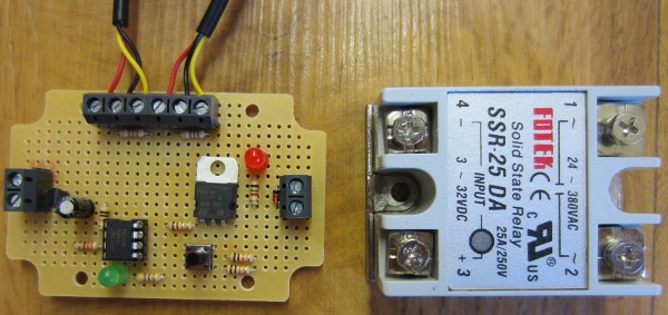
solar water heating controller for pool with solid state relay

Pictured above is a second version which we subsequently made for a special order which is designed to control an solid state relay (SSR) instead of the usual on board mechanical relay since this was to be used with a large mains powered pump which pushes water from a swimming pool in France around 12 solar water heating panels.

The type of relay pictured has four screw-on terminals. To close the relay you supply <20mA of 3-32VDC to two of the terminals, and that effectively shorts out the other two terminals (though in reality it does not ‘short out’, it just allows AC voltage of 24-380 VAC to pass internally through it into one terminal and out of the other).

As they are not mechanical, solid state relays tend to last longer, switch faster, and use less power. They do however generate/release some heat, they are more expensive, and this type of external relay needs to be housed in a suitable enclosure as it switches mains electricity.

Click here find out more or buy a solid state relay now. Prices start from around £5 each.

Project of the Day – Thermostat Controller for Innovative AC Cooler

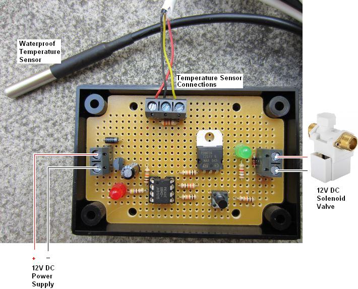
Today we have worked on a thermostatic controller which is used to open a solenoid valve when the temperature measured by a sensor exceeds a user set level.

programmable thermostat to control a 12V DC solenoid valve

This controller is for a telecoms company which have servers in a data centre which are cooled by air conditioning (AC). The AC units are located outside an office in an area from which heat cannot escape, and so it builds up eventually causing the AC units to fail.

Four years ago when we first heard from this company, they had set up a Hozelock irrigation system on a timer to spray water mist around the AC units from 8am to 7pm on workdays, but they wanted something thermostatically controlled so that water would only be used to cool the AC units when it was actually necessary.

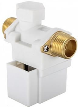
12 volt dc solenoid valveWe provided them with a complete solution including enclosure, 12VDC solenoid valve, controller, and a waterproof temperature sensor (an LM335 we sealed with epoxy into stainless steel tubing – the method for its manufacture is explained here: Make a Waterproof Temperature Probe). This has worked very well ever since reducing the peak temperature of the data centre by 6 degrees Celcius. However, after 4 years in all weathers the temperature sensor has started to become unreliable, and the company also wanted some modifications to the programming of the controller so that the water mist can be triggered at lower temperatures.

The new controller which was pictured above now uses a commercial waterproof DS18B20 digital temperature sensor and we also substituted a MOSFET for the relay which was on the original unit so that the whole controller is now solid state. This controller should help to keep the AC units cool for a good few years to come.

The use simply uses the button on the controller to set the threshold temperature above which the misting is to be turned on (settable in 1 degree steps from 25 degrees Celcius). After 10 seconds of the temperature being measured over this threshold the misting will start, and it will run until the temperature falls by a couple of degrees.

Project of the Day – Digital Competitive Shooting Range Timer

We have just finished working on a digital timer for competitive shooters to use at the range, but this type of timer could be turned to many different applications with minimal alteration.

In front of the shooter is a table with a pressure pad which detects the presence of a gun resting upon it. When the gun is lifted, the timer starts and the shooter attempts to hit each of five targets in turn. When the fifth and final target is hit, the target closes a micro-switch which stops the timer, and the time taken to hit the five targets is displayed.

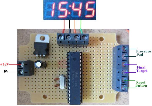
Connecting diagram for arduino 7 segment 4 digit timerIn order to complete this project we needed an accurate timer and minimal wiring complexity, so we used the Arduino system but using its ATmega328 microcontroller chip as a standalone with external 16MHz clock crystal and capacitors, and an L7805 5V voltage regulator instead of using a full Arduino board.

The maximum time to be recorded by the timer is 90 seconds. (Typically shooters will have a limit of 50 seconds to hit all five targets, but may take up to 90 seconds initially.) We therefore needed a 4-digit display to show the seconds and hundredths of seconds of the elapsed time up to a maximum of 90:00.

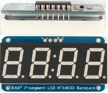
Adafruit 7 segment 4 digit display with backpack

We chose the excellent Adafruit 7-segment 4-digit i2c display with Backpack. This device has its own chip which does all the hard work and means that only two output pins from the Arduino are needed to drive the display (clock and data) together with a 5V and 0V connection to power it.

The accuracy of the timer comes from using the Arduino millis() function which returns the number of milliseconds the sketch (program) has been running. The exact time when the gun is lifted from the pressure pad is noted, and each time the display is refreshed (every tenth of a second) the start time is subtracted from the current time to display the time elapsed since the shooter picked up the gun. When the final target is hit, the start time is subtracted from that time and left on the display until everything is reset for the next shooter.

If you need something like this please email neil@reuk.co.uk.