Bricking a Beaglebone Black

In a previous article we introduced the Beaglebone Black – a low power, low cost, credit card sized Linux computer available in the UK for around £35 and just $45 in the USA. We have been using the Raspberry Pi since it was first released in early 2012, so we were very interested to try out this similarly priced alternative which promised greater processor speed, 2GB of on board eMMC flash memory for the operating system, and most importantly for the work we do, 7 analog (ADC) inputs compared to zero on Raspberry Pi.

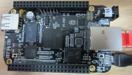
Beaglebone Black - low cost Linux computer

We received our Beaglebone Black (pictured above) around a week ago, and have been playing around with it in any spare time. Getting it set up was very quick and easy following the instructions served up as a webpage from the BBB itself. But then today something went wrong.

While looking on the internet to find any recommendations/suggestions for a VNC (virtual networked computing) server for the BBB I found this recent blog posting by Roger Meike which went through the steps he took to successfully install the X11 VNC server on his Beaglebone Black. This enabled him to interact with its full graphical interface / desktop through his Mac instead of having to hook the BBB up to a separate monitor or TV or only being able to use the command-line interface terminal via SSH.

So, step one, connect the Beaglebone Black to the ethernet cable and USB cable – check everything is working as it should via SSH.  Step two, update and upgrade the Ångstrom Linux distribution installed on the Beaglebone. So far so good – seemingly. The command opkg update took very little time to run to completion; the command opkg upgrade took the best part of an hour and a half to run, but didn’t show any errors, and after it was completed everything was working as it had previously – no problems evidenced at all.

Before embarking on the X11 VNC server installation I decided to reboot the Beaglebone Black, so I entered the reboot command. Next time I looked at the BBB a few minutes later 3 of the 4 user indicator LEDs were fixed on instead of their usual flashing. I attempted to SSH in but could not connect, and entering http://192.168.7.2 via my web browser (which is the usual way of accessing the BBB when it is connected to your computer via USB) resulted in ‘This webpage is not available’ error message.

Unresponsive Beaglebone Black after update and upgrade

It appeared that something had gone wrong somewhere, but the start up guide mentioned that the LEDs are fixed on while the eMMC is being flashed with a new distribution from the SD card and that process can take up to 45 minutes. On the off chance that upgrading the distribution without the SD card results in the same thing (and not wanting to turn it off if it was actually doing something), I left the BBB alone for a couple of hours, but the LEDs just stayed on.

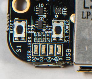
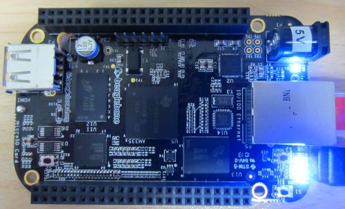
I next pressed the on board reset button. The LEDs turned off, then one turned on (PWR LED), then another turned on (labelled D2), and then a few seconds later LEDs D3 and D4 turned on and stayed on permanently.

Beaglebone black user LEDs

Next I unplugged the USB cable and left the Beaglebone Black disconnected from the power that cable supplies for a few minutes. When I reconnected the USB cable to the computer, nothing happened – the computer could not see the BBB whereas it previously recognised it immediately as a USB mass storage device when it was connected. But the LEDs still came on.

I tested there was nothing wrong with the USB port on the computer – it was fine; I tried connecting the BBB to alternative USB ports on the computer, and still nothing, just the LEDs permanently fixed on.

I then hooked the BBB to a monitor via HDMI, but still nothing. It seems that it has turned into an illuminated brick.

Looking around on the internet I found this guide to unbricking Beaglebone Black without Erasing eMMC, as well as comments from other people who have run into similar problems with their BBB. It seems the only way to fix this is to download the latest Ångstrom distribution on another computer, unzip it, get an image writer for Windows, write the image to the SD card, boot from the SD card, and then wait for the image to be copied across to the eMMC. But, this requires a microSD card which I don’t have, and a lot more time. Also, quite a few stories of people going through this process and ending up with an un-bootable BBB. Is it necessary to do this every time the distribution needs updating??

I’ve never had any problems with any Raspberry Pi, and I have some which have been running continuously for months without crashing or any other issues. Therefore this bricked Beaglebone Black is going to be returned – not to be exchanged for another Beaglebone, not for a refund, but for another Raspberry Pi. Sometimes the grass is not greener on the other side – I just wish that the Raspberry Pi GPIO included some analog inputs!

As Nigel D wrote regarding the advantage of Pi over BBB: having the boot stuff and OS on removable media means that bricking the board is that much more difficult, makes it easier to experiment between different operating systems, and makes full backup and recovery easier.
Raspberry Pi Temperature Datalogger with DS18B20 Sensor

We’ve been adding more Raspberry Pi related articles to the REUK.co.uk website over the last week covering GPIO – connecting sensors to the Pi, and also controlling relays connected to the Pi from the internet

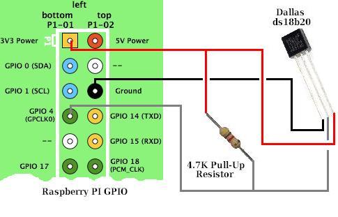
Raspberry Pi GPIO DS1B20 temperature sensor connectionsNow we have moved on to cover temperature sensors, a very important part of the work we do relating to solar water heating systems. Being able to control a pump based on the temperature of one or more sensors is very powerful, but Raspberry Pi makes it (relatively easy) to also monitor those sensors over the internet and track the exact state of the system in real time remotely while also logging the data.

We have recently added this article on using the DS18B20 1-wire digital temperature sensor with Raspberry Pi: DS18B20 and Raspberry Pi. (Note that Raspberry Pi only has digital, no analog inputs – therefore we use digital temperature sensors with Pi rather than the analog LM335 temperature sensors we use with our primary solar water heating pump controller product.)

Raspberry Pi temperature data logger with Xively

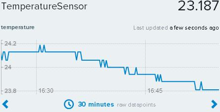
We also added a second article which shows how you can feed the temperature readings from the DS18B20 connected to the Raspberry Pi for to be logged and visualised by cloud service Xively: Raspberry Pi Temperature Datalogger with Xively.

When we have finished publishing these introductory Raspberry Pi articles, we’ll then move on to articles showing how to pull the techniques explored together to make renewable energy related devices with Raspberry Pi – e.g. wind speed dataloggers, solar controllers, energy monitors, energy saving automation devices, and much more.

Low Voltage Disconnect with Display and Datalogger

Our user-programmable low voltage disconnect (LVD) circuit remains one of our most popular products – very useful to protect batteries from deep discharge damage.

One request we have received many times is for an LCD (liquid crystal display) to be added to our low voltage disconnect circuits so that the actual voltage of the battery being monitored is shown together with other useful information such as the low voltage disconnect set point, state of the system, and so on.

A second request is for some datalogging of the voltages measured – ideally to be displayed on an LCD. Therefore we have developed a new REUK low voltage disconnect circuit with LCD and data logger to meet both of those requirements.

low voltage disconnect with LCD and data logger

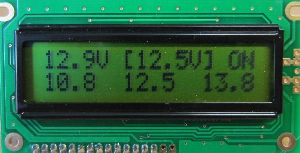
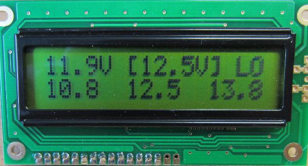
We have attempted to make this device as useful as possible while being as simple as possible to use. The LCD pictured above from our prototype shows (from top left to top right) the current voltage measurement (updated every 0.1 seconds), the target voltage for change of state (in this example 12.5V is the voltage below which the low voltage disconnect will engage), and the state (in this case, output ON).

The bottom row shows the data from the data logger, from left to right, minimum voltage logged, average (arithmetic mean) voltage logged, and maximum voltage logged.

The voltage measured is logged once every just over 7 minutes, with the most recent 200 measurements logged. That gives a 24 hour record of the battery voltage which is very useful for identifying problems and understanding battery usage.

reuk LVD with LCD and data logger

In the screenshot above, the state is now ‘LO’ since the measured voltage (11.9V) is below the LVD voltage (12.5V). After 10 seconds of this state being maintained, the output would be turned off automatically and only turn back on after 10 seconds of the measured voltage exceeding the LVD cancellation voltage.

The user can easily set the disconnect voltage and cancellation voltage using the display and a button on the LVD circuit, and the datalog can also be cleared by the user. All data is retained by this LVD circuit even when it is disconnected from the battery.

If you are interested in purchasing a low voltage disconnect circuit with display and datalogger, email neil@reuk.co.uk with details of your exact requirements.

Project of the Day – Wind Turbine Dynamic Blade Pitch Controller

Today we have been working on a dynamic pitch control system for a wind turbine generator. Dynamic pitch enables the blades of a wind turbine to be rotated into or out of the wind to increase or decrease the amount of wind energy they can exploit. It is used for power control in some of the largest commercial wind turbines, but the controller pictured below is to be used on an off grid DIY 3kW wind turbine generator charging an 800Ah 48V battery bank in Murcia, Spain.

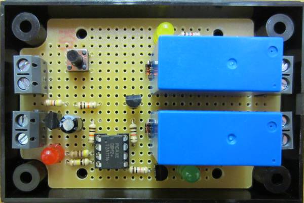
wind turbine dynamic blade pitch controllerThe designer, owner, and builder of this wind turbine has housed a 24VDC epicyclic motor inside the main shaft with slip rings to connect cables from the bottom of the mast to the turbine. This motor can turn the individual wind turbine blades clockwise or anti-clockwise, and he fitted limit switches at the position of maximum rotation in either direction to limit their motion.

At the top of the mast by the turbine generator is a 12V DPCO relay which is used to switch the +24V and 0V connections to enable the direction of the motor to be changed. When that relay is energised the motor turns one way, and when the relay is not energised the motor turns the opposite way.

He also has an anemometer (wind speed measuring device) which closes a relay when the wind speed exceeds 5 mph.

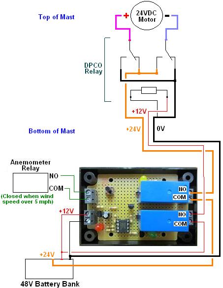
Schematic for wind turbine dynamic pitch control systemThe schematic above shows how our controller fits into the system. 12V (nominally) is tapped from the 48V battery bank, and the exact voltage measured. If the voltage exceeds a user programmed set point (13.5V) then we want the turbine blades to turn out of wind to reduce the power going into the battery. If the voltage is less than the set point then we want the turbine blades to be turned into the wind to try to increase the power going into the battery.

There are two relays on our controller: one switches +12V to the DPCO relay to dictate the direction the motor will turn, and the other switches the +24V (tapped from the 48V battery bank) which will power the motor.

If the wind speed is low (as measured by the anemometer) then the motor is not turned. If the wind speed is good then if the battery voltage is high the motor is powered for 1/4 of a second to turn the blades a little out of the wind, and if the battery voltage is low the motor is powered for 1/4 of a second to turn the blades a little into the wind. The limit switches override this setup so if the blades are already at their limit, the motor will not try to turn them past the limit.

This process is repeated every couple of seconds to keep everything as efficient as possible while protecting the batteries from overcharging.

Follow Up to RC Helicopter Lighting Controller

A few weeks ago we put together an automatic lighting controller for a radio controlled helicopter – see here for details on that project: RC Helicopter Lighting Controller.

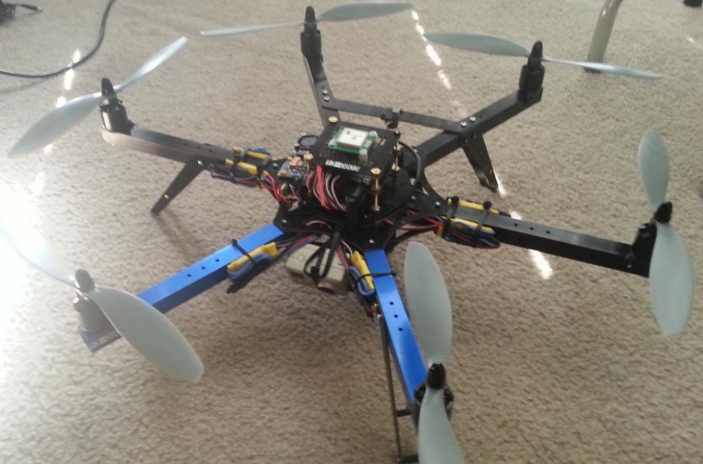
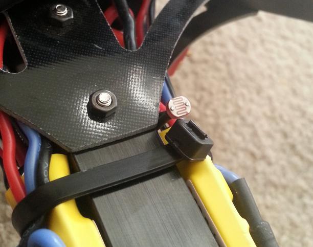
That controller has now been successfully installed on the RC helicopter. Here are a couple of photographs – first the helicopter and secondly a view of the light detector mounted to it. We also have a video of the navigation lights coming on and turning off automatically according to ambient lighting conditions. Thanks to Troy for those.

rc helicopter automatic navigation lights rc-helicopter-light-detector

Low Voltage Disconnect – User Programmable Set Points in Binary

Our REUK Programmable Low Voltage Disconnect (LVD) is a product which is used to protect batteries from being excessively discharged and therefore permanently damaged. The user of this device can set the voltage at which the low voltage disconnect is activated, and a second higher voltage at which it is cancelled.

In programming mode, each button press reduces the low voltage by 0.1V from a default value of 12.5V, or increases the cancellation voltage by 0.1V from a default value of 12.0V. For example, they would press the button 7 times to set the low voltage to 11.8V (12.5-0.7V) or 9 times to set the cancellation voltage at 12.9V (12.0+0.9V).

This method of user data entry works very well as it is simple and much cheaper than using a digital display or digital keypad BUT where it does not work so well is in situations where the low voltage is to be set very low, or the cancellation voltage very high – for example, to set a low voltage of 10.0V would require 25 button presses. That is not convenient, and so many button presses increases the likelihood of the user making a mistake.

low voltage disconnect with binary entry of cut out and cut in voltages

To get around this occasional issue we have come up with an alternative design (prototype pictured above) which enables the user to enter the voltage set points using binary via a couple of buttons with corresponding red and green LEDs.

Let’s say someone wants to set the low voltage set point to be 12.4V. Removing the decimal point gives us 124 which is 1111100 in binary (just type a number followed by ‘in binary‘ in google to find out its binary value). The user enters this binary value pressing the red button for a ‘0’ and the green button for a ‘1’. The LEDs then replay the sequence of 1’s and 0’s for visual confirmation of correct data entry, and that’s it – the unit is programmed.

More Technical Detail

We were going to use an 8-bit value for the voltage entry, but that gives a maximum value of binary 11111111 which is 255 in decimal. Since we want our LVD’s to be suitable for 24V battery systems without software modification, 25.5V is almost always going to be too low and so 8 bits is simply not enough. Therefore we changed the design to 16-bit (maximum decimal value 65535) but this means that for the expected maximum voltage of 30.0V we have for the decimal value of 300 a 16-bit binary value of 0000000100101100. This has a lot of leading zeroes which again increases the chance of the user making a mistake – therefore in the final design the user enters the binary value starting with the least significant bit (i.e. going from right to left) and any leading zeroes (which are now following zeroes) are added automatically by the microcontroller.

For example, if a user with a 24V battery system wanted a cancellation voltage of 27.4V, they would type in the Google search box convert 274 to binary and get the following result:

convert decimal value to binary

The leading 0b just tells you that what follows is in binary – 100010010. The user then uses the red and green buttons to enter this binary value starting from right to left 0-1-0-0-1-0-0-0-1, and that is it – 27.4V has been successfully saved in the device.

Project of the Day – Swimming Pool Solar Water Heating Controller with Max Temperature

Today we have been working on a new solar water heating pump controller for use with a swimming pool with a user-settable maximum water temperature. This can be used to keep hot tubs at a safe temperature, or keep a swimming pool from getting unpleasantly hot.

This new device is based around our latest 2013 Solar Water Heating Pump Controller with the new features added on.

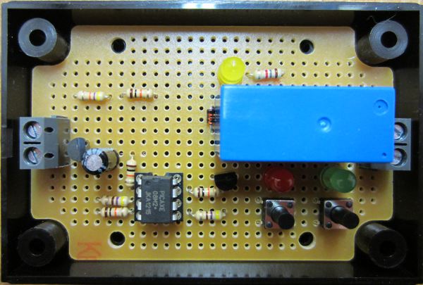
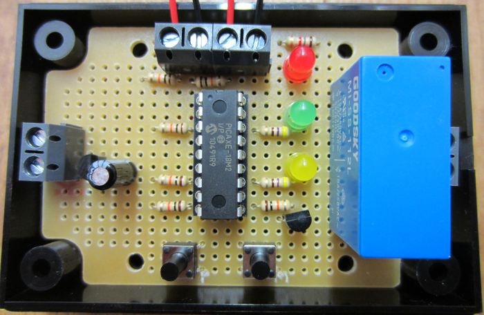
Swimming pool solar water heating controller with max temperature controlIn terms of hardware we have moved from a PICAXE-08M2 to a PICAXE-18M2 for its additional input/output pins, and then just added the yellow LED and second push button.

The operation of the controller is unchanged from the 2013 controller with the addition of the following functionality:

User can set maximum temperature the pool should reach to 1 degree accuracy from 25 degrees Celcius up.

If pool reaches the maximum temperature, the pump will turn off and not turn on again until the pool temperature has fallen by at least 2 degrees Celcius (hysteresis).

User can disable the maximum temperature feature or enable it with the push of a button.

If you need a controller of this type for your solar heated pool or hot-tub, do not hesitate to contact us via the REUK.co.uk website.

Multiple Buttons/Switches on one ADC Input

Small microcontrollers are cheap and easy to use, but one problem they have is a shortage of IO pins (input output). If you have a lot of inputs (e.g. sensors, switches, buttons etc), and outputs then a larger (more expensive) microcontroller is often required.

There is a good way around this problem when there are a lot of switches or buttons to detect; an example is shown below with three push to make buttons:

multiple switches connected to one microcontroller pin ADC

Instead of connecting the buttons to separate digital input pins on the microcontroller, each button can instead be connected up to different value resistor as shown above, and the combined output connected to an ADC (analogue digital converter) pin on the microcontroller.

When no buttons are being pressed, the ADC pin sees 0 volts thanks to the pull down resistor. If the top button is pressed, a voltage divider is formed with R1=47K and R2=10K, so the ADC pin sees 0.877V. If the middle button is pressed, a voltage divider is formed with R1=10K and R2=10K, so the ADC pin sees 2.500V. And if the bottom button is pressed, a voltage divider is formed with R1=1K and R2=10K, so the ADC pin sees 4.540V. The ADC pin monitors the voltage and by comparing the detected voltage with the known values for each button, the microcontroller will know which button has been pressed.

This is an excellent technique to use for up to around 10 buttons. Just remember that if more than one button is likely to be pressed at the same time things get a lot more complicated – particularly when there are a lot of buttons.

Standalone Arduino on a Breadboard

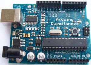
arduino duemilanove microcontroller board

We have used Arduino boards in many of our projects. For those that do not know, Arduino is described as an open-source electronics prototyping platform and is basically a microcontroller on a preassembled board with a good selection of IO (inputs and outputs) and availability of shields (add-on circuit boards to help with internet connectivity, motor control, and much more) which can be connected. The boards have a USB socket through which code is downloaded to the board and also to enable control of devices via a PC.

Although Arduino boards are relatively cheap, starting from around £10 each (click here for best priced Arduino boards), things start to get expensive when you do multiple custom embedded projects – particularly when you are not using the majority of the features provided on the board.

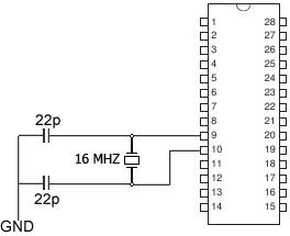
Fortunately it is possible to buy the microcontrollers which are found on the Arduino boards separately, add just a few components (a clock crystal, and a couple of capacitors), and build the rest of your project around that.

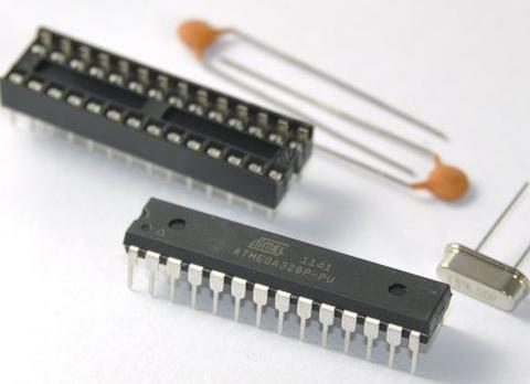
standalone arduino kit - microcontroller, crystal, and capacitors

The common Arduino duemilanove board for example has an ATMEL ATmega 328 microcontroller which are easy to purchase BUT a blank microcontroller is not enough. It must have the correct Bootloader (software) on it before you can use it with the Arduino programming environment and USB connection. This is a job you can do yourself (with an ISP programmer), but for most people it will be much easier and cheaper just to purchase a kit such as the one pictured above which we use and available here for around £3 (Arduino Bootloader Kit). These have the bootloader pre-installed on the microcontroller and include a PCB socket, and the capacitors and the external 16MHz clock crystal.

Standalone Arduino circuit

Using these kits means you only need one Arduino board which you use to download your code sketches to the microcontroller. You then unplug the microcontroller from the Arduino board and plug it in on your own project board.

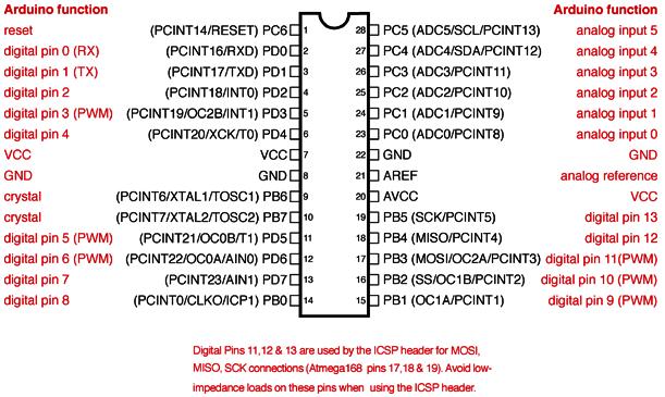
Below is the ATmega168 / ATmega328 Arduino pin mapping diagram so you know which pins on the microcontroller correspond to the inputs and outputs labelled on an Arduino board.

arduino atmega328 and atmega168 pin mapping

Project of the Day – RC Helicopter Lighting Controller

Today we made a controller to turn on the navigation lights on a radio controlled helicopter when it is dusk or dark outside.

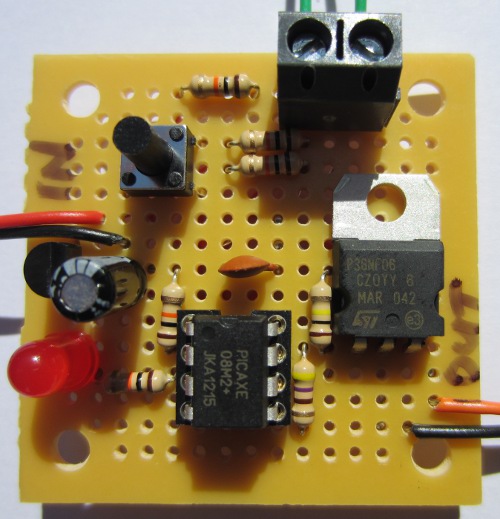
RC Helicopter lighting controller

Being a small RC helicopter, the lighting controller had to be small in size and low weight. A basic transistor circuit with light detector would not have been up to the job since the navigation lights would flicker on and off when the light detector was at the ambient light/dark threshold. The controller therefore needed hysteresis to avoid this multi-switching. It also needed to be easy for the user to set the light/dark threshold at which the navigation lights turn off/on.

To keep everything small, we used a PICAXE-08M2 microcontroller for this project. To set the light/dark threshold we decided against using a potentiometer in case vibrations from the helicopter’s motor caused it to rotate away from the user set position. Instead we fitted a small tactile switch to the circuit board. If this is pressed and held (at dusk) while the controller is being connected to the battery pack, the light detector (mini LDR) measures the current ambient light level and stores this in memory (not lost when battery disconnected) as the light/dark threshold.

In standard operation, when the light level is measured to be brighter than the threshold continuously for two seconds, the output to the navigation lights is turned on. If subsequently the light level is measured to be duller than the threshold continuously for two seconds, the output to the navigation lights is turned off.

The dimensions of the controller are under 2 x 2 inches.