Standalone Arduino on a Breadboard

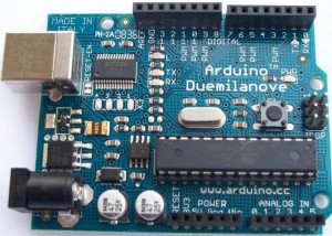
arduino duemilanove microcontroller board

We have used Arduino boards in many of our projects. For those that do not know, Arduino is described as an open-source electronics prototyping platform and is basically a microcontroller on a preassembled board with a good selection of IO (inputs and outputs) and availability of shields (add-on circuit boards to help with internet connectivity, motor control, and much more) which can be connected. The boards have a USB socket through which code is downloaded to the board and also to enable control of devices via a PC.

Although Arduino boards are relatively cheap, starting from around £10 each (click here for best priced Arduino boards), things start to get expensive when you do multiple custom embedded projects – particularly when you are not using the majority of the features provided on the board.

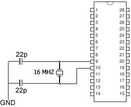
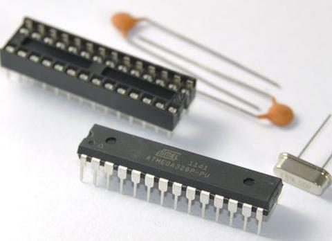
Fortunately it is possible to buy the microcontrollers which are found on the Arduino boards separately, add just a few components (a clock crystal, and a couple of capacitors), and build the rest of your project around that.

standalone arduino kit - microcontroller, crystal, and capacitors

The common Arduino duemilanove board for example has an ATMEL ATmega 328 microcontroller which are easy to purchase BUT a blank microcontroller is not enough. It must have the correct Bootloader (software) on it before you can use it with the Arduino programming environment and USB connection. This is a job you can do yourself (with an ISP programmer), but for most people it will be much easier and cheaper just to purchase a kit such as the one pictured above which we use and available here for around £3 (Arduino Bootloader Kit). These have the bootloader pre-installed on the microcontroller and include a PCB socket, and the capacitors and the external 16MHz clock crystal.

Standalone Arduino circuit

Using these kits means you only need one Arduino board which you use to download your code sketches to the microcontroller. You then unplug the microcontroller from the Arduino board and plug it in on your own project board.

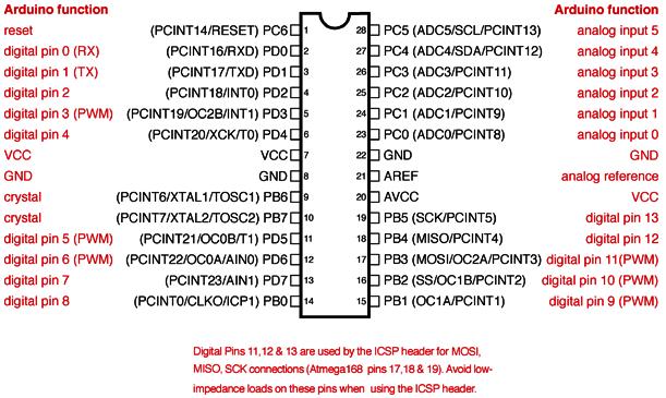
Below is the ATmega168 / ATmega328 Arduino pin mapping diagram so you know which pins on the microcontroller correspond to the inputs and outputs labelled on an Arduino board.
arduino atmega328 and atmega168 pin mapping

Project of the Day – Use Surplus PV with Air Source Heat Pump

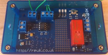
Since the introduction of feed in tariffs in the UK we have been selling our REUK Solar PV Immersion Controller (pictured below) the concept of which is described in our article Water Heating with Surplus Solar PV.

REUK solar PV immersion controller

This device uses a light detector to estimate the level of solar electricity generation, and if it exceeds a user set threshold it switches on an immersion heating element so that electricity generated in excess of what is needed can be used to heat water rather than being exported (sold) to the Grid for just a few pence per unit.

An immersion heating element is a very simple resistive heater which can be turned on and off repeatedly during the day (with fluctuating levels of solar generation) without coming to any harm. If instead our standard controller is to be used to switch an air source heat pump (ASHP) or similar complex device then there could be problems.

One of our customers wanted to use our controller to power his air source heat pump with surplus PV solar generation, but in discussions with the manufacturer was told that the ASHP should be run for at least 30 minutes each time it is turned on. We therefore modified our controller software so that after the ASHP turns on (following a period of consistent good solar generation) it will stay on for 25 minutes, and then only turn off after a 5 minute period during which 90% of the light level readings show bad solar generation.

The result of these changes is that there will be times when the electricity demanded by the ASHP exceeds solar generation and so electricity will have to be imported (bought) from the Grid to meet the shortfall. But, as air source heat pumps cost thousands of pounds, it is much more important to protect the equipment from damage than to worry about the few extra pounds incurred in importing mains electricity.

Special Offer – Complete Evacuated Tube Solar Water Heating System

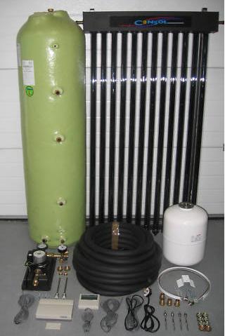
Complete evacuated tube solar water heating system

Pictured above is a complete DIY 30 tube evacuated tube solar water heating system for sale here in the UK at £1,662 plus £45 for delivery.

While that obviously sounds like a lot of money (as it is) you get a lot for your money all from one place thereby making savings in postage and the time otherwise taken to spec and source everything.

Evacuated tube solar water heating systems (click link for more information from REUK site) are the most efficient on the market today. A 30 tube system such as this fitted with a 200 litre tank will meet the majority of a typical family household’s hot water needs for 3 seasons of the year, and make a good dent in water heating bills the rest of the time – even when it is freezing outside.

The kit comprises the 30 evacuated tubes, 200 litre insulated twin coil cylinder, roof fittings, solar contoller and pumping station, expansion vessel, pipework, and all the other fittings necessary to put together a complete solar water heating system together with detailed instructions.

Click here for more information or to buy now: 30 tube solar water heating kit. There are many other options – e.g. smaller or larger systems available from the same seller. Click here to view the range: DIY evacuated tube solar water heating.

Testing Car Battery Voltage Meter

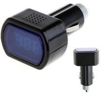
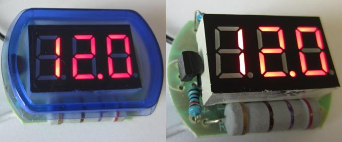
LED car battery voltmeterPictured above is a car battery voltage meter which is designed to be inserted into the cigarette lighter socket of a vehicle to test and display the battery voltage – purchased for £1.76 including delivery from Hong Kong.

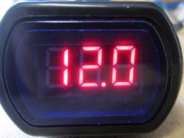
It is relatively well made if a bit plasticky, but certainly as good as should be expected for a device at this sort of price. Inserting it into the car cigarette lighter socket it displayed the battery voltage accurately to well within 0.1V, and when tested with a variable power supply gave similarly reliable readings with an input voltage from 6V to 16V.

LED voltmeter for 12V car battery

The LED numerical display is bright – if anything too bright as the voltmeter draws 40mA when it is on which is too high to leave connected to a battery all the time (taking 1Ah of charge from the battery per day).

We purchased this to test and to take apart for a project. Breaking it open was very easy.

taking apart an LED voltmeter

The plastic end cap is threaded onto the positive end of the cigarette lighter plug, and can be unscrewed (with a bit of force). Inside is a 5A fuse which should really be a 100mA fuse to properly protect the device.

Then the two sections of black plastic can then be prised apart to expose the innards.

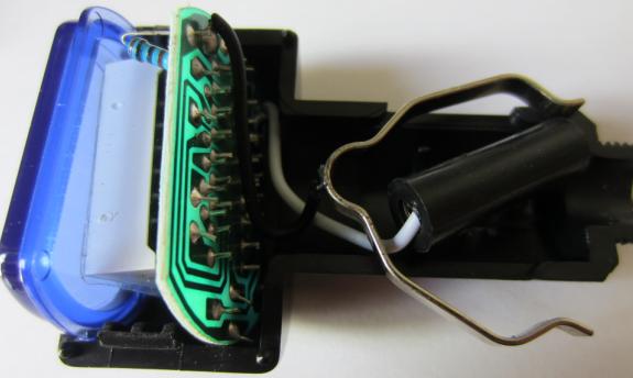
Components inside the LED voltmeter

There is a small circuit board with an IC on it, the LED display, a large resistor, some other common components, and a TL431 adjustable precision zener shunt regulator which is used as the voltage reference.

We wanted this to stick on top of a solar charged 12V lead acid battery to display the battery voltage so we chopped off all the unnecessary bits and pieces leaving just the two wires for connection to the + and – terminals of the battery.

mini LED voltmeter for 12V batteryThe blue plastic cover is pretty much vital as without it it is very difficult to read the voltage from the display.

Finally, to reduce power consumption, we wired a small push to make button to the white positive input cable and connected that and the black negative cable to the terminals of the battery. Now, whenever the button is pressed and held, the battery voltage is displayed. This mini LED battery voltmeter is only 3.5 x 2.5 x 1.0 centimetres in size and does the job perfectly.

If you are interested in buying one of these car cigarette lighter LED voltmeters click here.

80 Watt 12V Monocrystalline PV Solar Panel – £69.98 inc Delivery!

Special offer of the week has to be these 80 Watt power monocrystalline PV Solar Panels offered as a pre-order item (to be despatched after 17th April 2013).

80 Watt Solar Panel - Special Offer

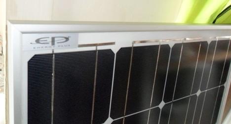
The panel, pictured above, has an anodised aluminium frame, 3.2mm tempered glass, and is 824 x 669 x 35mm and just 8kg. Best of all is the price – £64.99 plus £4.99. It comes fitted with standard MC4 terminated cables. It is fully weatherproof for outdoor use.

Click here for more information or to snap up one or more of these panels now: 80 Watt 12V PV Solar Panel.

L298N Dual H Bridge Motor Drive Controller

An H Bridge is a electronic circuit which has an output voltage which can be in either direction. This is particularly useful when used with motors as reversing the polarity of the power supply to a motor causes it to rotate in the opposite direction.

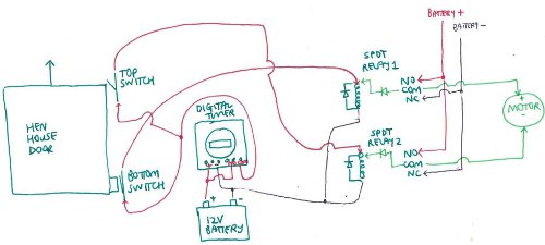
In our article Automatic Hen House Door Controller we showed how  a pair of relays could be used to achieve this polarity reversal for motors, as making an H bridge can be a bit complicated and mistakes tend to lead to destructive short circuits. Fortunately now there are many ready made H bridge boards available relatively cheaply which make everything a lot simpler for the DIYer.

dual h bridge for motor control

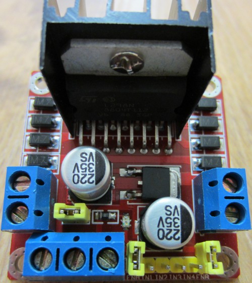
Pictured above is one such H Bridge circuit. Like most it is actually a dual / double H Bridge and so it can be used to control the direction of motion (and on/off status) of one or two motors.

The row of three screw in-terminals pictured at the bottom of the image are for the +12V and GND input connections, and a +5V output connection respectively. The +5V comes from an onboard 5V regulator which can be used to directly power a microcontroller such as an Arduino or Picaxe which would usually be used to control the motor(s).

The pair of terminals on the left of the image connect to the two power inputs of the first DC motor, and the second pair of terminal on the right to the second motor (if used).

There are 4 yellow inputs on the bottom right of the board as shown in the image labelled IN1, IN2, IN3, and IN4. If a high logic signal is sent (by the microcontroller) to IN1, the first motor will turn in one direction. If a high logic signal is sent to IN2 then the first motor will turn in the other direction. IN3 and IN4 work in the same way with the second motor.

It is not actually necessary to use a microcontroller – microswitches and resistors can be used to control the motor(s) in some simple applications.

underside view of dual h bridge motor controller

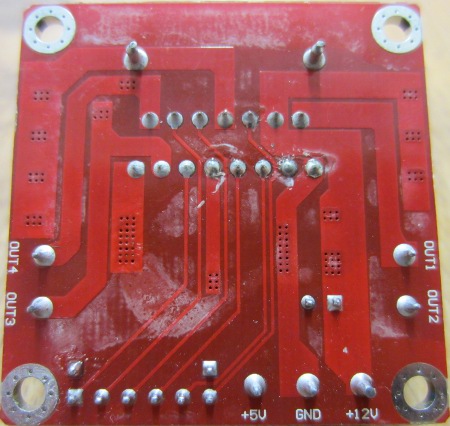
This H Bridge circuit is based around the L298N from ST Microelectronics – a dual full bridge driver which can supply up to 2 Amps of output current to each motor.

Click here to purchase one of these: Dual H Bridge Boards. Prices start from just £2.50 including delivery (air mail from China – 3 weeks) to up to £10 from UK sellers. As it typically costs around £5.00 to purchase just the L298N chip from electronics suppliers in the UK, these boards are great value and speed up project development no end.

Testing LM2596 Variable Voltage Regulator

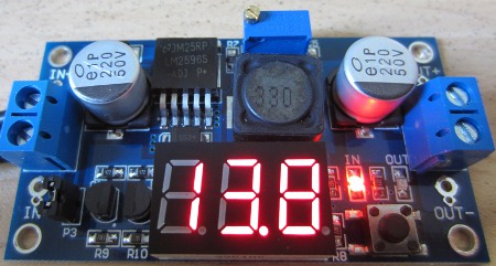
Our LM2596 Variable Voltage Regulator (discussed previously here: regulator with display) has finally arrived after its long journey from China.

LM2596 variable voltage regulator with display

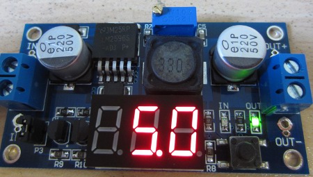
The first image above shows the input voltage as being 13.8V (which was accurate to <0.1V). The second image below shows the output voltage which we set by adjusting the small brass screw in the blue potentiometer to be 5.0V (which was also accurate to <0.1V).

lm2596 with LCD voltage display

The build quality and quality of the components used is excellent throughout, the LCD is bright, and the addition of a red LED and a green LED to indicate whether the input or output voltage is being displayed is very useful. Selecting whether to display input or output voltage is achieved using a small button on the regulator board. In addition to screw-in terminals for connection of the input and output wires, there are also holes with solder pads in both fine and medium sizes so that different sizes of wire can be more securely attached if required.

The only bad point would be that there is no option to turn off the LCD when it is not needed – i.e. it needs three options (display input voltage, display output voltage, or display nothing) instead of the two it has. The LCD draws approximately 25mA all the time, so will take 0.6Ah of charge out of a battery every 24hrs which is a lot. Another 10mA seems to be the quiescent current lost in the regulator when nothing is connected to the output but it is still regulating voltage.

We can think of many uses for these voltage regulators which are made easier thanks to the on board display – first and foremost for small battery charging from a 12V battery, and/or powering USB charged devices (using a 5.0V output). For battery charging of say four series connected NiMH rechargeables, you would just set the output voltage to say 5.8 or 5.9V and connect it to the battery pack with the correct polarity.

Apart from having slightly high self-power consumption, these regulators are excellent quality and fantastic value.

If you are interested in purchasing one of these regulators, click here: LM2596 Voltage Regulators. Prices are around £3.50 each or £17 for five including air mail delivery from China.

9V from 12V Regulator Module – Alternative to L7809

About six months ago a Chinese company on eBay had a special offer selling the item pictured below for US$2 each. We bought five and put them somewhere safe and then forgot what they were for.

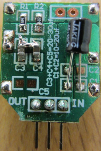
L7809 alternative - high current 4 Amps 9V output regulatorA quick test today showed them to be efficient 9V from 12V regulators working much the same as the common L7809 regulator.

With a bit of searching around we finally found the details for this product. It is an high current voltage regulator which takes an input voltage of from 12-23 VDC and outputs 9 VDC. No heat sinking is required up to a constant 2.5 Amps of output current, and they are rated to supply brief peaks of up to 4 Amps.

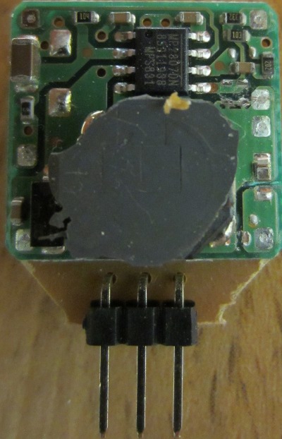
9V from 12V regulator module - 4 Amps

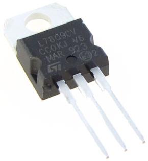
The pin connections (the three legs) have 2.54 mm (0.1 inch) pitch exactly the same as for the L7809 regulator, and the device is also of similar overall dimensions. Therefore, this little PCB can be used to substitute an L7809 (pictured below) where more current than the 1-1.5 Amps (with heat sink) maximum of the L7809 is required.

L7809 voltage regulator


It could for example also be used instead of the LM317T we use in our standard 9V from 12V regulator (though we have designed that with R1 = 330, R2 = 2K8 so that we get an output of around 8.8V compared to the 9.3V this regulator module outputs – a lower voltage to reduce power consumption for renewable energy powered applications). With thicker cables for the connections this would give a 2.5 Amp constant current 9V from 12V regulator with no need for heat sinking.

This module has a small integrated circuit labelled MP2307DN which a quick search on Google shows up as a 3A constant load current DC-DC step-down power supply module and a monolithic synchronous buck regulatorwhich has been used in this case to provide a 9V output.

At the time of writing we can only find this device here: L7809 Alternative Module priced at US$4.99 plus US$1.99 for air mail delivery. (The same vendor also has similar L7812 and L7833 alternative modules for 12V and 3.3V outputs respectively.)

Project PCB Boards for 18-pin PIC Microcontrollers

We use microcontrollers every day for many of our projects, mostly 8-pin but quite often 18-pin for the more complex products we are requested to design and build. We have found the following products to be particularly helpful for prototyping and for one-off projects – 18-pin project PCBs from UK company RK Education.

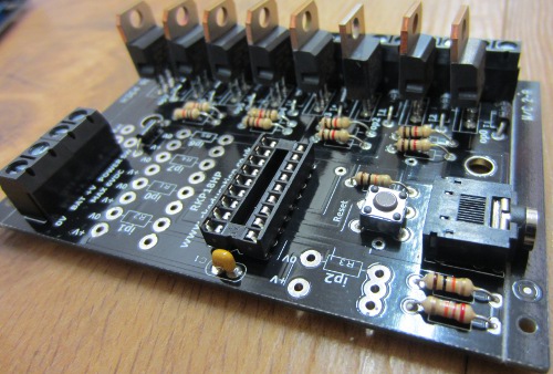
RKP18HP 18 pin PIC PCB with power transistors

Pictured above is a RKP18HP board designed for use with 18-pin microcontroller such as PICAXE. This board gives 5 inputs, and 8 TIP121 power transistor outputs for high power applications. It is supplied with a software download socket to get your code onto your microcontroller.

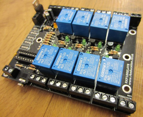
Below is the RKP18Relay8 board which is again designed for 18-pin microcontrollers and takes up to 5 inputs and controls 8 SPDT relays each with LED indicators to show then they are energised. Again the software download socket is provided.

RKP18Realy8 18-pin 8 SPDT relay PCB

These items are available as just boards (PCB) or as full kits and are very competitively priced – transistor board £1.19, kit £3.49; relay board £2.00, kit £10.99. The kit prices include all the components shown – e.g. all the relays, screw in terminals, LEDs, resistors, etc, so all you need to add is your choice of 18-pin microcontroller and you need some solder and a soldering iron.

The power transistor board takes about 10-15 minutes to solder together, and the relay board around 15-20 minutes. Full instructions are provided and the PCBs are well labelled so it is difficult to make any mistakes.

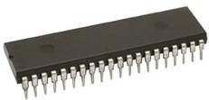
picaxe 40x2 microcontroller

Many other boards are also available for low power applications, smaller and larger microcontrollers, and much more. For a one off 28-pin or 40-pin microcontroller project (e.g. PICAXE 40X2 as pictured above) the corresponding boards with large prototyping areas are particularly useful.

Take a look at the RK Education website here.