Project of the Day – Well Pump Float Switch Fail Safe Controller

Today we put together a fail safe protection system for a well pump used to fill a header tank for a domestic water supply. This fail safe is designed to be connected in series with the existing pump controlling Stuart Turner float switch to cut the power to the pump if the header tank is about to overflow. If the primary float switch sticks or otherwise fails and does not turn off the pump when it should, the fail safe system will override it and turn off the pump.

The heavy duty MONO pump in this particular system is rated at 1hp (0.73kW) and pumps water up from from a well 15 metres below the header tank at a rate of 10 gallons per minute. Therefore a float switch failure and the subsequent flood of water overflowing the header tank and going through the house could be extremely serious and costly.
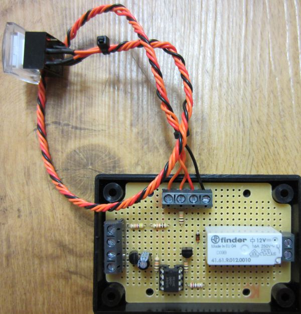
fail safe protection for well pumpPictured above is the solution we came up with. A secondary float switch is fitted into the header tank just above the existing float switch. In normal operation, this secondary float switch is closed which keeps a relay on our controller closed through which the mains live passes on its way to the existing primary float switch.

If the level of the water in the header tank reaches the secondary float switch, the float rises up which opens the switch. This causes the relay on our controller to open cutting the live connection to the primary float switch and therefore to the pump keeping it turned off.

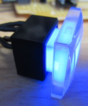
button with integrated LED

We have added a button (pictured above) which under normal operation can be used to test the fail safe for peace of mind – pressing the button causes the relay to open and the LED in the button to light up for a few seconds.

If the fail safe is triggered by high water then the pump turns off and the LED in the button turns on to give a visual warning that something has gone wrong. The home owner must then check the header tank, remove any obstruction from the primary float switch, confirm that float switch is working reliably, and then press the button to manually reset the fail safe. There is no automatic reset of the fail safe as this would be far too risky – flood damage was averted and now manual intervention is a must.
Solar Water Heating Pump Controller with Solid State Relay

A few days ago (link to the article) we described our new solar water heating pump controller based around our standard 2013 controller, but fitted with waterproof digital temperature sensors for use in pools, hot-tubs, and so on.

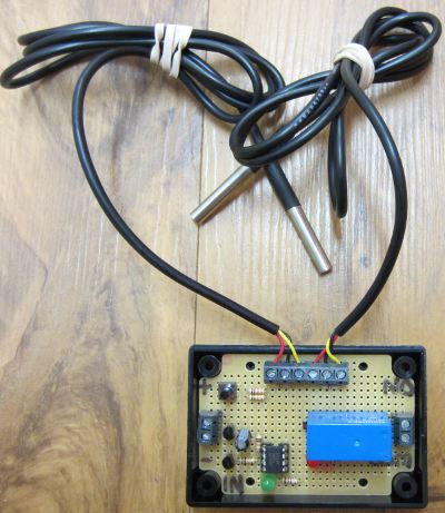
solar water heating controller for pool with solid state relay

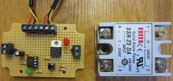
Pictured above is a second version which we subsequently made for a special order which is designed to control an solid state relay (SSR) instead of the usual on board mechanical relay since this was to be used with a large mains powered pump which pushes water from a swimming pool in France around 12 solar water heating panels.

The type of relay pictured has four screw-on terminals. To close the relay you supply <20mA of 3-32VDC to two of the terminals, and that effectively shorts out the other two terminals (though in reality it does not ‘short out’, it just allows AC voltage of 24-380 VAC to pass internally through it into one terminal and out of the other).

As they are not mechanical, solid state relays tend to last longer, switch faster, and use less power. They do however generate/release some heat, they are more expensive, and this type of external relay needs to be housed in a suitable enclosure as it switches mains electricity.

Click here find out more or buy a solid state relay now. Prices start from around £5 each.

Project of the Day – Thermostat Controller for Innovative AC Cooler

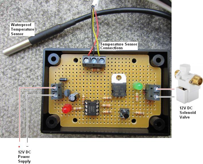
Today we have worked on a thermostatic controller which is used to open a solenoid valve when the temperature measured by a sensor exceeds a user set level.

programmable thermostat to control a 12V DC solenoid valve

This controller is for a telecoms company which have servers in a data centre which are cooled by air conditioning (AC). The AC units are located outside an office in an area from which heat cannot escape, and so it builds up eventually causing the AC units to fail.

Four years ago when we first heard from this company, they had set up a Hozelock irrigation system on a timer to spray water mist around the AC units from 8am to 7pm on workdays, but they wanted something thermostatically controlled so that water would only be used to cool the AC units when it was actually necessary.

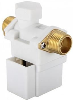
12 volt dc solenoid valveWe provided them with a complete solution including enclosure, 12VDC solenoid valve, controller, and a waterproof temperature sensor (an LM335 we sealed with epoxy into stainless steel tubing – the method for its manufacture is explained here: Make a Waterproof Temperature Probe). This has worked very well ever since reducing the peak temperature of the data centre by 6 degrees Celcius. However, after 4 years in all weathers the temperature sensor has started to become unreliable, and the company also wanted some modifications to the programming of the controller so that the water mist can be triggered at lower temperatures.

The new controller which was pictured above now uses a commercial waterproof DS18B20 digital temperature sensor and we also substituted a MOSFET for the relay which was on the original unit so that the whole controller is now solid state. This controller should help to keep the AC units cool for a good few years to come.

The use simply uses the button on the controller to set the threshold temperature above which the misting is to be turned on (settable in 1 degree steps from 25 degrees Celcius). After 10 seconds of the temperature being measured over this threshold the misting will start, and it will run until the temperature falls by a couple of degrees.

New Solar Water Heating Pump Controller with Waterproof Sensors

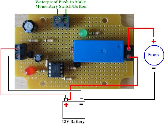
Pictured below is our new solar water heating pump controller with waterproof sensors. It is heavily based around our standard 2013 Solar Water Heating Pump Controller, but modified to use waterproof DS18B20 digital temperature sensors in place of the LM335 analog temperature sensors we normally use.

Solar water heating pump controller with waterproof temperature sensorsAs it can take up to 0.75 seconds for the controller to get a reading from a DS18B20 sensor, and since sometimes digital sensors output spurious data, there have been some modifications made to the logic which decides when the circulation pump should be turned on and off, but all the original functionality of the 2013 controller has been retained.

This controller is ideally suited for use with swimming pool and hot tub solar water heating systems as well as many other applications where having waterproof temperature sensors is essential.

We will shortly be adding this new product to the REUK Shop, but in the meantime, if you are interested in purchasing this controller or something similar to meet your exact requirements, email neil@reuk.co.uk.

Project of the Day – Low Voltage Disconnect for Powered Snorkel

Today’s project was a very particular low voltage disconnect for a powered snorkel system for recreational divers. The diver’s face mask is connected to a 5 metre long hose which is in turn connected to a buoy floating on the surface. A 12V battery powered diaphragm pump forces air from the surface down to the diver to breathe. Using such a system as opposed to scuba has the benefit of requiring no certification, gives a safe fixed maximum diving depth, and is lightweight and non-polluting.

6 volt 8ah agm battery

The system is powered by two series-connected 6V 8Ah AGM batteries (a type of deep cycle battery which is sealed and can be used inverted) and gives 1 hour of dive time before needing to be recharged. The problem is how to let the diver know that the battery is low and protect the batteries from being overly discharged.

A piezo type warning buzzer could not be used since in a group of divers underwater it would be very difficult to ascertain whose buzzer was sounding, and a warning light would not work since this system would be used in tropical waters in bright daylight at shallow depths.

A generic low voltage disconnect could also not be used since it would just cut off the pump and therefore the air to the diver with no warning when the battery voltage breeched the set low voltage level. Instead something was required which would over the course of a few minutes cycle the pump on and off to reduce the air pressure to the diver forcing them up to the surface. (The system is an open circuit with a rebreather bag, and so turning the pump on and off reduces the pressure of the air supplied, but does not result in there being sufficient air one second, and then no air at all the next.)

There are commercial PWM (pulse width modulation) solutions available, but they are very expensive and could not give the exact shut down sequence desired – bringing the air pressure down to 90%, 80%, 70%, 60%…and so on over three minutes when the battery voltage gets low.

powered scuba low voltage disconnect controller

Therefore we made the special low voltage disconnect controller pictured above. This device constantly monitors the battery voltage, and when it falls and remains below a set threshold (11.2 Volts) the shut down sequence begins.

For 20 seconds the pump is off for 1 second then on for 9 seconds, off for 1s then on for 9s. Then for the next 20 seconds the pump is off for 2 seconds on for 8 seconds, off for 2s on for 8s. This process is repeated every 20 seconds increasing the pump off time and therefore reducing the air pressure to the diver so they have to surface, but can do so safely and without panicking.

Project of the Day – Digital Competitive Shooting Range Timer

We have just finished working on a digital timer for competitive shooters to use at the range, but this type of timer could be turned to many different applications with minimal alteration.

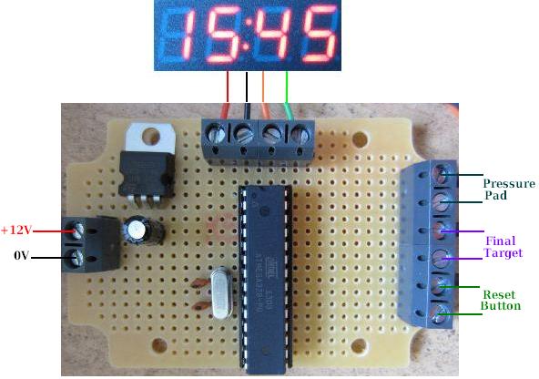
In front of the shooter is a table with a pressure pad which detects the presence of a gun resting upon it. When the gun is lifted, the timer starts and the shooter attempts to hit each of five targets in turn. When the fifth and final target is hit, the target closes a micro-switch which stops the timer, and the time taken to hit the five targets is displayed.

Connecting diagram for arduino 7 segment 4 digit timerIn order to complete this project we needed an accurate timer and minimal wiring complexity, so we used the Arduino system but using its ATmega328 microcontroller chip as a standalone with external 16MHz clock crystal and capacitors, and an L7805 5V voltage regulator instead of using a full Arduino board.

The maximum time to be recorded by the timer is 90 seconds. (Typically shooters will have a limit of 50 seconds to hit all five targets, but may take up to 90 seconds initially.) We therefore needed a 4-digit display to show the seconds and hundredths of seconds of the elapsed time up to a maximum of 90:00.

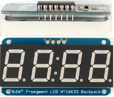
Adafruit 7 segment 4 digit display with backpack

We chose the excellent Adafruit 7-segment 4-digit i2c display with Backpack. This device has its own chip which does all the hard work and means that only two output pins from the Arduino are needed to drive the display (clock and data) together with a 5V and 0V connection to power it.

The accuracy of the timer comes from using the Arduino millis() function which returns the number of milliseconds the sketch (program) has been running. The exact time when the gun is lifted from the pressure pad is noted, and each time the display is refreshed (every tenth of a second) the start time is subtracted from the current time to display the time elapsed since the shooter picked up the gun. When the final target is hit, the start time is subtracted from that time and left on the display until everything is reset for the next shooter.

If you need something like this please email neil@reuk.co.uk.

Project of the Day – 12V High Power Regulator with LT1084CP-12

We supply a lot of low dropout 12V regulators – primarily for use with LED lighting when powered from 12V batteries (particularly in vehicles) to get a clean 12.0V output. These regulators are limited to around 0.7 Amps maximum output.

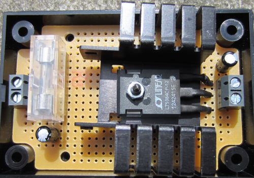
HIgh current 12V regulator based around Linear LT1084CP-12 regulator

The regulator pictured above is a special order 2 Amp rated low dropout regulator for someone who was unable to split a lighting circuit into multiple lower current circuits for regulation with our standard regulators.

It is based around the LT1084CP-12 low dropout regulator from Linear Technology. This IC is rated to supply up to 5 Amps, but it has a higher maximum rated dropout (the voltage difference between target voltage and input voltage below which output voltage falls below target voltage) than the LM2940 chips we use in our regular 12V regulators – 1.5V compared to just 0.5V with the LM2940. (The recommended minimum input voltage for the LT1084CP-12 is 13.5V.)

This higher dropout will not be a problem in this particular application since a) power will be coming from a vehicle battery – therefore maintained constantly at near full charge and voltage, b) only 2 Amps at most will be drawn from the regulator resulting in a dropout of 1V at most, and c) the output is to power LED lighting so if the voltage of the battery were ever to fall to a low charge level, the lighting would just be a a tiny bit dimmer – no harm done.

Click here for the LT1084CP-12 datasheet for more information, or here to purchase this chip: buy LT1084CP-12.

Raspberry Pi Temperature Datalogger with DS18B20 Sensor

We’ve been adding more Raspberry Pi related articles to the REUK.co.uk website over the last week covering GPIO – connecting sensors to the Pi, and also controlling relays connected to the Pi from the internet

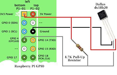
Raspberry Pi GPIO DS1B20 temperature sensor connectionsNow we have moved on to cover temperature sensors, a very important part of the work we do relating to solar water heating systems. Being able to control a pump based on the temperature of one or more sensors is very powerful, but Raspberry Pi makes it (relatively easy) to also monitor those sensors over the internet and track the exact state of the system in real time remotely while also logging the data.

We have recently added this article on using the DS18B20 1-wire digital temperature sensor with Raspberry Pi: DS18B20 and Raspberry Pi. (Note that Raspberry Pi only has digital, no analog inputs – therefore we use digital temperature sensors with Pi rather than the analog LM335 temperature sensors we use with our primary solar water heating pump controller product.)

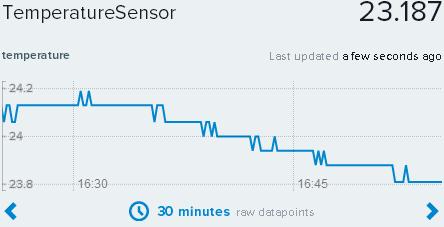
Raspberry Pi temperature data logger with Xively

We also added a second article which shows how you can feed the temperature readings from the DS18B20 connected to the Raspberry Pi for to be logged and visualised by cloud service Xively: Raspberry Pi Temperature Datalogger with Xively.

When we have finished publishing these introductory Raspberry Pi articles, we’ll then move on to articles showing how to pull the techniques explored together to make renewable energy related devices with Raspberry Pi – e.g. wind speed dataloggers, solar controllers, energy monitors, energy saving automation devices, and much more.

New Raspberry Pi Category on REUK.co.uk Website

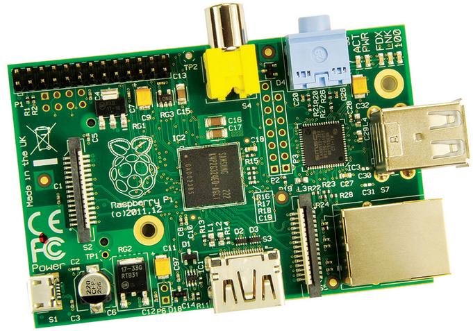
raspberry pi model b

We have been doing a lot of work recently with Raspberry Pi so we have decided to start uploading a collection of new articles on Raspberry Pi and its uses in renewable energy and other projects.

There is already a lot of information out there on the internet, but we will be covering the first steps from opening the box to doing useful work with Raspberry Pi.

Our first article in this series is here: Connecting to Raspberry Pi from PC via SSH in which we show you how to interact with a Raspberry Pi from a Windows PC so that you do not need to invest in an HDMI cable, extra keyboard, and mouse. Click here for the Raspberry Pi category article list.

Low Voltage Disconnect with Display and Datalogger

Our user-programmable low voltage disconnect (LVD) circuit remains one of our most popular products – very useful to protect batteries from deep discharge damage.

One request we have received many times is for an LCD (liquid crystal display) to be added to our low voltage disconnect circuits so that the actual voltage of the battery being monitored is shown together with other useful information such as the low voltage disconnect set point, state of the system, and so on.

A second request is for some datalogging of the voltages measured – ideally to be displayed on an LCD. Therefore we have developed a new REUK low voltage disconnect circuit with LCD and data logger to meet both of those requirements.

low voltage disconnect with LCD and data logger

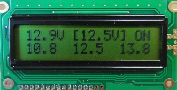
We have attempted to make this device as useful as possible while being as simple as possible to use. The LCD pictured above from our prototype shows (from top left to top right) the current voltage measurement (updated every 0.1 seconds), the target voltage for change of state (in this example 12.5V is the voltage below which the low voltage disconnect will engage), and the state (in this case, output ON).

The bottom row shows the data from the data logger, from left to right, minimum voltage logged, average (arithmetic mean) voltage logged, and maximum voltage logged.

The voltage measured is logged once every just over 7 minutes, with the most recent 200 measurements logged. That gives a 24 hour record of the battery voltage which is very useful for identifying problems and understanding battery usage.

reuk LVD with LCD and data logger

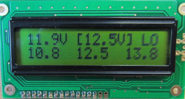
In the screenshot above, the state is now ‘LO’ since the measured voltage (11.9V) is below the LVD voltage (12.5V). After 10 seconds of this state being maintained, the output would be turned off automatically and only turn back on after 10 seconds of the measured voltage exceeding the LVD cancellation voltage.

The user can easily set the disconnect voltage and cancellation voltage using the display and a button on the LVD circuit, and the datalog can also be cleared by the user. All data is retained by this LVD circuit even when it is disconnected from the battery.

If you are interested in purchasing a low voltage disconnect circuit with display and datalogger, email neil@reuk.co.uk with details of your exact requirements.