Controller for Poultry Incubator

Pictured below is an automatic controller for a poultry incubator. The eggs in this incubator must be kept within a tightly regulated temperature range, they need to be automatically turned at regular intervals, and there is also a fan to be controlled.
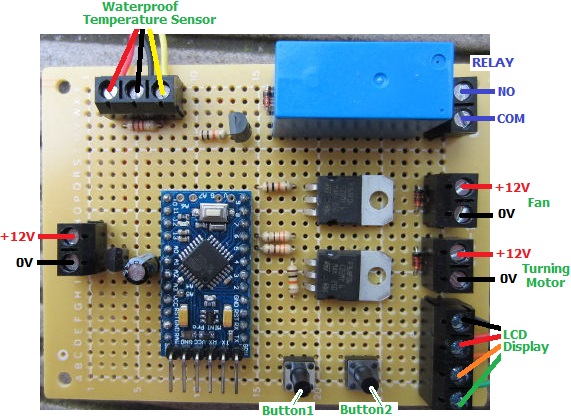
thermostatic poultry incubator control boardThe owner of this incubator would like the temperature of the eggs to be kept between 37 and 37.5 degrees Celcius, so there is a heating element which is switched by an on board relay following the temperatures measured by a DS18B20 waterproof sensor.

The eggs are to be turned every 30,45,60, or 75 minutes, and to do this the motor must run each time for a few seconds. Both of these timing intervals can be set by the user.

The fan has three modes of operation – on, off, or automatic, and in automatic mode the user can select an interval of 5, 10, or 15, etc minutes on and minutes off repeating.
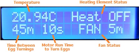
Display for thermostatic poultry incubator controllerAll of the current settings and system status are shown on a backlit 16×2 LCD display (see above), and all user settings are programmed using this display and the two buttons on the controller board.

If you need a controller of this type, please email neil@reuk.co.uk with details of your exact requirements. For details of an alternative incubator controller which also controls humidity, click here: Poultry Egg Incubator with Humidity Sensor.
Automatic Shooting Target Time Controller

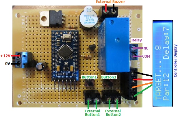
Pictured below is a controller designed for competitive shooters to automatically turn targets on the range to face to and away from the shooters for the required length of time.

shooting-range-target-controllerThe targets are controlled by air solenoids. When these are energised the targets face away from the shooter, so our controller has a relay with NC and COM connections (normally connected). When the relay is energised, the NC-COM connection breaks and the targets turn to face the shooter.

After pressing a button to start the timer, there is a user selected delay of 3 or 7 seconds. Then the relay is energised to turn the targets to face the shooters and a buzzer sounds for half a second. The targets are kept facing the shooters for a user selected ‘par’ time of 1,2,3,4…15, 25, 35, 90, 165, or 210 seconds. Then the relay is de-energised, the targets turn away, and the buzzer again sounds for half a second. The system then resets ready to be used again.

Pressing the other button acts as an override so that the targets can be kept facing the shooter until the button is pressed again to cancel the override.

range-controller-targets-turnedAn LCD display is provided to make setting up the device with the required delay time and par time easy, and also to show a countdown of the number of seconds remaining during the two countdowns when the system has been triggered. It also constantly shows the current delay and par time settings to make the system easy to use.

We have added screw in terminals to the board so that a louder external buzzer/siren can be added, and so that external buttons can be mounted if the controller is to be housed in a waterproof box etc.

If you require a controller of this type (here is another of the competitive shooting timers we have made recently), please email neil@reuk.co.uk with details of your exact requirements.


Timer for Atlantic Crossing Balloon

Pictured below is a timer we made recently to help conserve battery power for the telemetry for an attempted balloon crossing of the Atlantic.

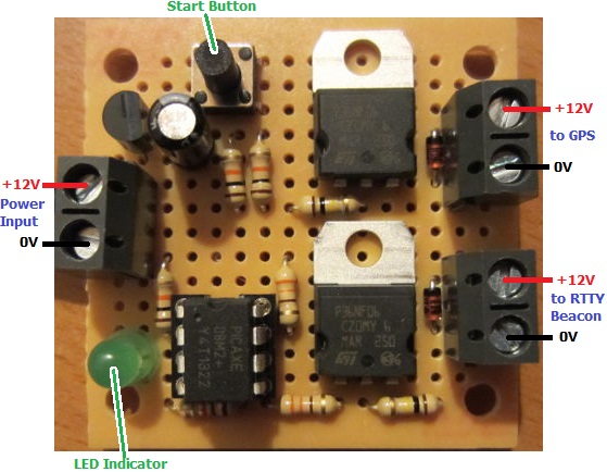
Timer for Atlantic balloon crossing telemetryThe payload of the balloon includes a GPS transmitter and an RTTY beacon so that the flight of the balloon can be tracked. Due to weight considerations, there is a limit to the size of the battery pack which can power these, and therefore there is a risk that the battery will run flat before the balloon (hopefully) lands in Europe after crossing the Atlantic from New York state.

Therefore, we were commissioned to make a secondary timer which would supply power to the RTTY beacon only for 15 minutes in every hour, and also to supply power to he GPS transmitter only when it is likely to be over land – for the first 7 hours and then again after a couple of days have passed. For this we used a PICAXE microcontroller because of its lower power consumption.

GPS module and RTTY beacon for Atlantic balloon crossing telemetry with ArduinoThe GPS and RTTY modules to be powered are pictured above connected to the Arduino Nano and Arduino Uno which control them – both relatively high power consumption devices themselves. Future flights will reduce weight and power consumption by connecting the GPS, and RTTY to a single Arduino which will also put itself into sleep mode to conserve power.

Balloon flight to near spaceWe were previously involved in an amateur balloon flight to the lower stratosphere reaching an altitude of 120,000 feet during which the picture above was taken which clearly shows the curvature of the Earth and the edge of the atmosphere. We made the timer which automatically severed the connection between the balloon and the payload after a fixed time to comply with FAA requirements.

DS18B20 Temperature Measurement with Spark Core

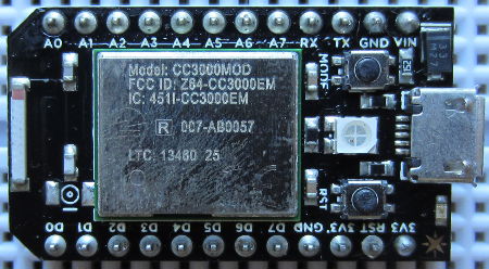
In our blog post Spark Core Introduction and First Impressions we introduced Spark Core – a Wi-Fi enabled Internet of Things device which can be programmed like an Arduino and accessed via the internet.

Spark Core Wi-Fi Open Source IoT development board

Of most interest to us at REUK is using Spark Core to enhance our range of solar water heating controller adding datalogging and internet functionality. Therefore we want to access temperature readings from DS18B20 digital temperature sensors of the type used in our 2014 Solar Water Heating Pump Controller connected to Spark Core.

As a test we connected a DS18B20 temperature sensor to the Spark Core. Pin 1 of the sensor connects to GND, Pin 3 to 3.3V, and Pin 2 to a digital pin on Spark Core – we randomly chose D2. Finally we connected a 4K7 resistor across Pins 1 and 3 of the sensor and entered the following code via the Spark IDE to flash to the Spark Core:

#include "spark-dallas-temperature/spark-dallas-temperature.h"
#include "OneWire/OneWire.h"
#define ONE_WIRE_BUS 2
OneWire oneWire(ONE_WIRE_BUS);
DallasTemperature sensor(&oneWire);

float temperature = 1.0;
char myStr[10];

void setup() {
 Spark.variable("read", &myStr, STRING);
 sensor.begin();
 sensor.setResolution(12);
}

void loop() {
 sensor.requestTemperatures();
 temperature= sensor.getTempCByIndex(0);
 sprintf(myStr,"%.3f",temperature);
}

At the time of writing (August 2014) it is not possible to have a Spark.variable which is a float – the code just will not compile – so the temperature measurement from the sensor (which is a float/double) must either be saved as an integer (losing accuracy due to rounding) or be converted into a string (which is what we did above to three decimal places with the sprintf function) so it can be accessed remotely.

We then wrote the following Python script on an internet connected Raspberry Pi to grab the temperature measurement once every minute and to append it to a text file for datalogging and later analysis:

#!/usr/bin/python

import urllib2
import json
import time

var = 1
while var == 1:
   response = urllib2.urlopen('https://api.spark.io/v1/devices/YOURDEVICEID/read?access_token=YOURACCESSTOKEN')
   html = response.read()
   reading = json.loads(html)
   temperature = reading['result']
   with open("core-temp-log.txt", "a") as myfile:
      myfile.write(temperature)
      myfile.write('\n')
   myfile.close();
   time.sleep(60)

The string variable read is the string conversion of the value read in by the temperature sensor.

Having got the Spark Core successfully reading data from a DS18B20 it is possible to fully replicate our Arduino based solar water heating pump controllers with the added benefit of internet connectivity and effective remote datalogging.

See our Raspberry Pi related articles Publish Temperature Sensor Readings to Twitter and Temperature Logger with Xively to find out how to automatically publish your collected data to the internet – either as a Twitter feed or with Xively as an online datalogger with graph plotting etc.

Solar Pump Controller with Diversion Valve

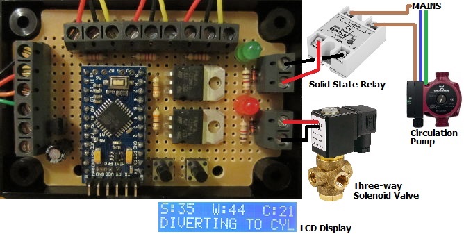
Pictured below is a solar pump controller we recently built to meet a specific requirement. A solar water heating panel is used to heat the water in a hot tub, but if the hot tub exceeds a maximum temperature for comfort, then any additional solar hot water is diverted to heat the contents of a cylinder used for domestic hot water.

Solar pump controller with diversion valveThis controller is closely based around our standard 2014 Solar Water Heating Pump Controller with LCD Display, but with the addition of a third sensor to measure the temperature of the cylinder (since we only want to send water from the solar panel to the cylinder if the solar water is hot enough to heat it up).

LCD display for solar water heating pump controller with diversion

If/when the temperature measured of the hot tub reaches or exceeds the user’s desired maximum for comfort, a three-way solenoid valve is energised automatically diverting the hot water from the solar panel to the cylinder . The pump then carries on pumping until either the hot tub’s temperature has fallen by a couple of degrees, or the solar panel cools to close to the cylinder temperature.

All sensors used are waterproof digital temperature sensors, and the display is enables the temperature of all three monitors to be constantly monitored. A solid state relay is used to switch the mains powered circulation pump on and off.

If you need a solar water heating pump controller, please take a look at the selection of units we have in the REUK Shop. If you do not find exactly what you need, please email neil@reuk.co.uk with details of your requirements.

Solar Pump Controller with Additional Sensors

Pictured below is a modified version of our standard 2014 Solar Water Heating Pump Controller with LCD.

2014 REUK Solar Water Heating Pump Controller with two extra temperature sensorsIn addition to the standard digital temperature sensors for the solar water heating panel and the hot water tank, this version adds a third sensor to measure ambient air temperature, and a fourth to measure the temperature of the top of the hot water tank.

LCD Display from REUK Solar Water Heating Pump Controller with two extra sensorsThe LCD display has been modified to show the solar and hot water tank temperatures for five seconds, and then the ambient air temperature and top of tank temperatures for five seconds. The bottom line of the display still displays system status and settings information to the user.

If you need a bespoke solar water heating pump controller, please email details of your requirements to neil@reuk.co.uk.

Rainwater Toilet Flush Pump Controllers with LCD

We have been making a bespoke range of controllers for people who would like to use rainwater for their toilet flushes for around 6-7 years now. Here is an example of one of our early Rainwater Toilet Flush System Controllers with details of how such a system works.

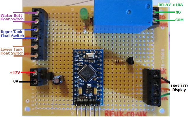
rainwater pump controller with LCD display and empty water butt sleep functionPictured above is one of our more advanced systems which includes an LCD display to keep the user up to date with the status of the system and water levels in the water butt and header tank (which gravity feeds to the toilet cisterns in the home).

In this particular case, if the two float switches in the header tank are not in water, the tank is empty, and so the pump turns on to fill the tank. If there is sufficient water in the water butt to fill the tank, then the pump will stop when the tank is detected to be full. If however the water butt is empty (or becomes empty during pumping), then then controller sleeps for four hours to allow a rain shower to collect a good amount of rainwater (if it rains in the meantime) so that pumping later will fill the tank.

rainwater controller system normal LCD displayThe display constantly shows the status of the water butt (WB) – either OK or LOW (empty), and the status of the header tank (HT) – either EMPTY, OK, or FULL. The bottom line of the display shows whether the pump is running, the controller is sleeping, or everything is just ticking along as it should.

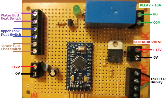
rainwater pump controller with mains water solenoid and LCD displayThe controller pictured above is a little more advanced. If the header tank is detected to be empty, then the pump will start as normal unless the water butt is also empty. If during pumping, the water butt becomes empty (or if it is already empty when the header tank is detected to be empty), a solenoid valve will close which will allow the flow of water up the rising main to enter the header tank to ensure that the toilets can always be flushed without any manual intervention.

rainwater controller with solenoid valve activatedThe display for this particular controller also shows the user when the solenoid valve is open so they know that you are using mains water due to a lack of stored rainwater in the water butt. There is no need for a four hour delay with this unit since every time the header tank empties and the water butt is either empty or becomes empty during pumping, the mains water supply will top up the header tank.

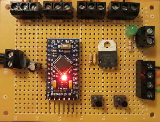
This controller is based around an Arduino Pro Mini microcontroller development board and uses standard horizontal float switches in the water butt and header tank to detect water levels.

If you need a rainwater toilet pump controller of any type, please email neil@reuk.co.uk with details of your specific requirements.

Pyboard Python for Microcontrollers

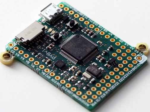
Pyboard python for microcontrollersPictured above is the Pyboard – an open source prototyping platform designed and manufactured in the UK. This board with its ARM microcontroller (STM32F405 clocked at 168MHz) is programmed using micropython a low memory usage version of the Python 3 scripting language.

The board has LEDs, microswitches, a built in accelerometer, and 30 general purpose IO connections (including 4 PWM, 14 ADC, I2C, and SPI pins) for connection to external components and analogue/digital sensors for your projects.

The board has 1MB of on board flash memory, 192KB of RAM, and also a micro SD card slot which can be used to store scripts and hold project generated data. It has a built in USB interface.

Pyboard fits in the marketplace somewhere between Raspberry Pi and Arduino. A Raspberry Pi is a full computer which means that it can be complicated to use, power hungry, and large in size. An Arduino is simple to use, has lots of useful GPIO and shields, and they are available in small versions, but they are not very fast and scripts need to be compiled on a PC before loading them to the Arduino. Pyboard is perfect for processor intensive stand alone projects – particularly for anyone who already has experience programming with Python.

Pyboard is just 33 x 40mm in size and weighs just 6g.

The official Micro Python website is here, and the tutorial which shows how to get strarted with Pyboard and Micro Python is here: Micro Python Tutorial.

REUK Super Timer with Light Detector Override

Pictured below is a new device which mixes the features of the REUK Super Timer 3 and the REUK Dawn/Dusk Lighting Controller.

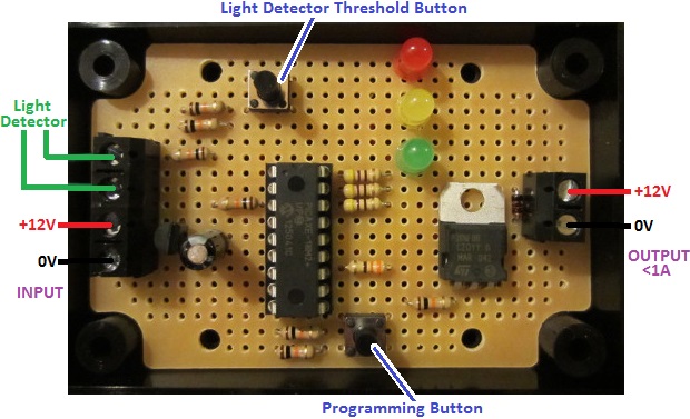
REUK Super Timer with light detector overrideThe timer can be programmed with different ON and OFF time durations from 1 second to 99 hours with various modes of operation available. When the time is ON, there is a 12V output (rated at up to 1A) which can be used to control up to 10-12 Watts of 12V devices, or used to switch a relay if higher currents or different voltages are to be switched.

The modification is the addition of a light detector (light dependent resistor) which is used to override the timer at night time. When the ambient light level is measured to be less than the user set threshold, then when the timer is ‘ON’ the output remains off.

This particular board is for an automatic fish feeder which directly drives a small motor, and the override is to prevent the feeder operating at night.

If you need a timer similar to this, email neil@reuk.co.uk with details of your exact requirements.

Low Voltage Disconnect with LCD Display

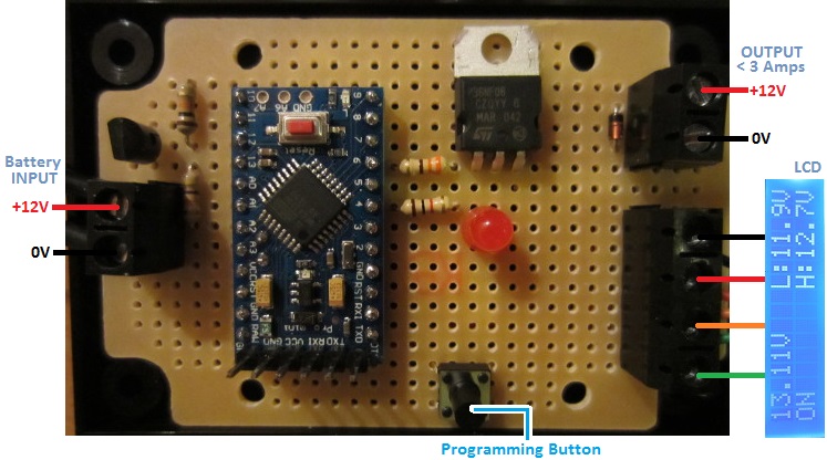
Pictured below is our latest low voltage disconnect circuit with LCD display.

REUK low voltage disconnect with LCD displayAs with our standard programmable low voltage disconnect (LVD), this device is designed to protect batteries from being discharged too deeply and permanently damaged. The user can set the low voltage at which the output loads will automatically be switched off, and also the higher cancellation voltage above which the output loads will be switched back on again.

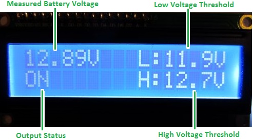
LCD display on REUK low voltage disconnect (LVD)This particular LVD has a backlit LCD on which system information is constantly displayed. It is also used when setting the low and high voltage thresholds which makes things  a lot clearer and simpler than using LEDs or a rotary switch to programme those in.

As shown above the display shows the measured battery voltage updated multiple times per second and given to 2 decimal places of resolution (and calibrated to be accurate to within +/- 0.02 Volts across the range 10-16V).

The system status is usually ON or OFF, but can also be LOW or HIGH when the battery voltage is transitioning one of the thresholds about to change the state of the system. The high and low threshold voltages are also permanently displayed.

In order to avoid the output cycling on and off too often (particuarly as the battery voltages can spike or dip depending on the loads they are powering) there is a time delay during which the voltage must remain under/over the voltage threshold before the system will change from ON to OFF or OFF to ON respectively. During that time delay the backlight of the display flashes as a visual indicator that the threshold has been breached. We chose to flash the display itself rather than flashing an LED either on the board or on leads, since it is much easier to panel mount just the LCD than to mount both that and an LED indicator.

This particular client-tailored LVD has a MOSFET directly switching the output loads which can have a maximum total rating of 3 Amps. We can also make this with a relay fitted on board for direct switching, or a lower rated output which can be used to energise a high current (or high voltage) rated relay external to the board – e.g. an automotive relay or a solid state relay (SSR).

This low voltage voltage disconnect with LCD is now available direct from the REUK Shop. Click here to find out more or to purchase now: buy REUK Low Voltage Disconnect with LCD.

We will shortly be adding a very similar unit with the addition of datalogging functionality. Over the last couple of years we have sold many LVDs with built in dataloggers (see here for an example: Low Voltage Disconnect with Display and Datalogger), and we now have refined things to the point that the product is ready for general sale. In the meantime, if you have any requirement for a low voltage disconnect with or without a display and with or without datalogging, please email neil@reuk.co.uk with details of your requirements.