Pyboard Python for Microcontrollers

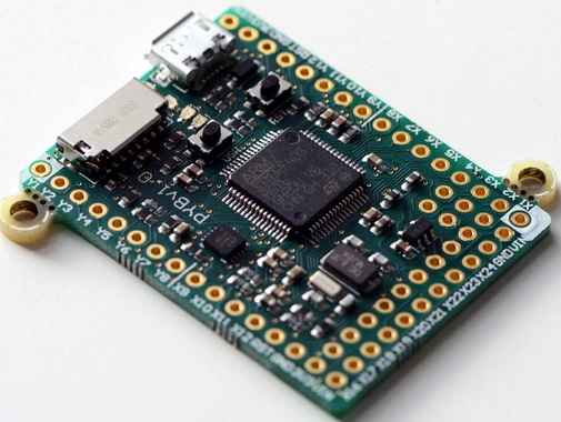
Pyboard python for microcontrollersPictured above is the Pyboard – an open source prototyping platform designed and manufactured in the UK. This board with its ARM microcontroller (STM32F405 clocked at 168MHz) is programmed using micropython a low memory usage version of the Python 3 scripting language.

The board has LEDs, microswitches, a built in accelerometer, and 30 general purpose IO connections (including 4 PWM, 14 ADC, I2C, and SPI pins) for connection to external components and analogue/digital sensors for your projects.

The board has 1MB of on board flash memory, 192KB of RAM, and also a micro SD card slot which can be used to store scripts and hold project generated data. It has a built in USB interface.

Pyboard fits in the marketplace somewhere between Raspberry Pi and Arduino. A Raspberry Pi is a full computer which means that it can be complicated to use, power hungry, and large in size. An Arduino is simple to use, has lots of useful GPIO and shields, and they are available in small versions, but they are not very fast and scripts need to be compiled on a PC before loading them to the Arduino. Pyboard is perfect for processor intensive stand alone projects – particularly for anyone who already has experience programming with Python.

Pyboard is just 33 x 40mm in size and weighs just 6g.

The official Micro Python website is here, and the tutorial which shows how to get strarted with Pyboard and Micro Python is here: Micro Python Tutorial.

Raspberry Pi GPIO Sensor Readings to Twitter

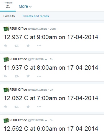
We have just published a new article Publish Temperature Sensor Readings to Twitter with Raspberry Pi to the REUK.co.uk website which includes full details on how to get sensor measurements from a Raspberry Pi up to the internet for remote viewing.

Raspberry Pi and TwitterWe will soon be returning to this to look at how batteries can be monitored, solar generation can be monitored, and many other similar projects.

We will then be showing how devices can be controlled from Twitter – for example, you could turn on your immersion heater element with a Twitter message if your Twitter feed tells you that your water tank is cold and you are on the way home and would like a hot bath.

Arduino Datalogger Testing

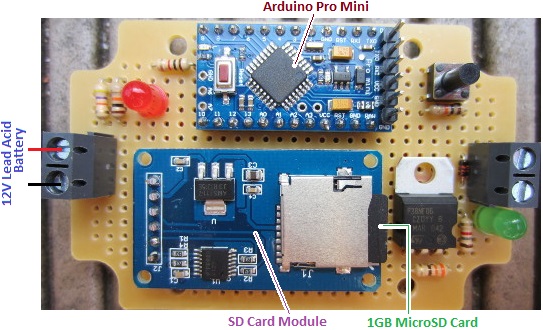
We recently built and tested a very simple SD card datalogger based around an Arduino Pro Mini – the smallest and cheapest Arduino board commonly commercially available. We have previously described datalogging to an SD card with an Arduino in our blog post Arduino SD Card Datalogging (to log temperatures). In this example we are instead logging the voltage of a solar charged battery used to power the lights in a shed.

REUK Arduino Battery Voltage Datalogger

The Arduino Pro Mini (£3) was programmed from a PC via an FTDI breakout board (£5), and connected to an Arduino micro SD module (£1) fitted with a 1GB micro SD card (£3).  Note that the unlabelled components in the image above are not required for this datalogger – we just built the controller so that it can later also be used as a low voltage disconnect.

We programmed the Arduino to read in the voltage of a 5Ah 12V SLA (via a 47K-10K voltage divider) and write it to a log file on the SD card once every second. The battery is connected to an 80 Watt PV solar panel via a solar charge controller. The battery is also connected to  three 1W LED spotlight bulbs which were left permanently on so that the battery would drain over night and be recharged during the day.

The datalogger was left connected to the battery from around 10:30am one day to around noon the following day in mid-April with blue skies both days.

USB memory card reader

In order to view the data collected on the micro SD card we just needed a USB all-in-one memory card reader (£1). Plug the micro SD card into the reader, plug the reader into a PC via USB, and download the collected data.

The collected data file (which was simply a list of voltages measured to 2 decimal places) was 97070 lines long with a file size of 680 kB. Therefore our 1GB card could have logged the battery voltage once a second for 3-4 years.

Looking through the datalog in a text editor it was obvious that the battery voltage did not change very fast at all. Therefore logging the voltage every second was unnecessary for this application – every 30 seconds or every 60 seconds would have been adequate.

Knowing from experience that plotting 100,000+ data points with Excel is usually an unhappy experience, I first copied the log file over to my Raspberry Pi, and ran the following sed script to create a new smaller file containing just every 60th record from the log file. (This is equivalent to having set up the datalogger to log the voltage once per minute in the first place.)

sed -n '0~60p' logfile.txt > 60slogfile.txt

This command took just 0.24 seconds on the Raspberry Pi (thanks to the raw speed of sed) and I then dropped the new smaller (1617 records) log file into Excel and made the following plot of the results.

Datalogger data collected from solar powered shed lighting

The vertical axis shows the measured voltage, and the horizontal axis shows time with the far left being 10:30am on day1 and the far right being noon on day2.

The plot shows how the solar charge controller carries out a bulk charge phase to rapidly charge the battery (peaking at 14.6V) and then maintains a float charge (around 13.6V) during the day while the solar generation far exceeded the charge used by the spotlights. At night the voltage of the battery drops rapidly down hitting a low of 11.95V before the sun rose high enough to start to charge the battery again.

If you need a voltage datalogger like this, a voltage datalogger with a built in low voltage disconnect to protect the battery from being too deeply discharged, or any other kind of single or multi-channel datalogger, please email neil@reuk.co.uk with details of your exact requirements.

Raspberry Pi GPIO with BerryIO

Today we have been trying out BerryIO – a control system for Raspberry Pi which is web browser based for ease of use and set up.

Although BerryIO can be used to monitor the system status of a Raspberry Pi; of most interest to use was the ability to easily control GPIO without any need for programming experience. This makes home automation via mobile phone, tablet, or desktop PC a realistic option even for relatively basic users.

Installation is achieved by entering the following commands at the prompt:

wget -N https://raw.github.com/NeonHorizon/berryio/master/scripts/berryio_install.sh
chmod +x berryio_install.sh
sudo ./berryio_install.sh

followed by:

berryio help

just to make sure it is working.

With BerryIO installed on your Raspberry Pi, you simply enter the IP address of the Raspberry Pi in the web browser on your phone, tablet, or PC, and after entering your Pi username and password when prompted you get a menu of options of which we found GPIO, camera (if you have one), and system status to be the most useful.

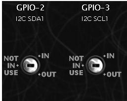
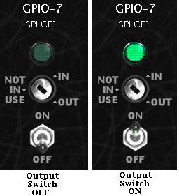
Raspberry Pi BerryIO - GPIO ControlSelecting GPIO from the menu, all of the GPIO pins are shown and you can set them individually to be either NOT IN USE, IN (for inputs), or OUT (for outputs).

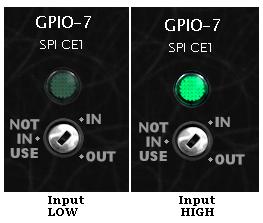
BerryIO GPIO inputs Raspberry PiIf you select IN for a pin (for example GPIO-7) as shown above, when a high signal arrives on GPIO-7 the green light turns on, and when the signal arriving is low, the green light is turned off. The web browser updates the status of the GPIO pins in real time – therefore no need to refresh the browser for updates.

Raspberry Pi GPIO outputs controlled from web browser BerryIOIf you instead select OUT for a pin, a toggle switch appears below the selector. Click on ON to turn on the output (green light illuminates for that GPIO pin in the browser), or click OFF to turn off the output (green light turned off).

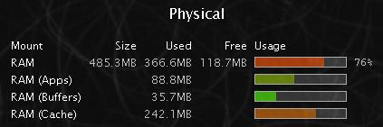
The system status shows a few bits and pieces of information about memory, storage, loads etc, but this does not currently update in realtime so you have to refresh the browser for the latest data.

raspberry pi system status - BerryIO

We will be looking into some useful real world useful applications for BerryIO, but it is certainly well worth installing it and having a play around with it just for fun.

BerryIO is still under development and new features and functionality are still being added to it. The release of an API for mobile app development should hopefully result in some interesting and useful tools being developed to control the Raspberry Pi remotely via a simple user interface.

Full details of BerryIO and the installation instructions are available here: install BerryIO.

GertDuino has Arrived

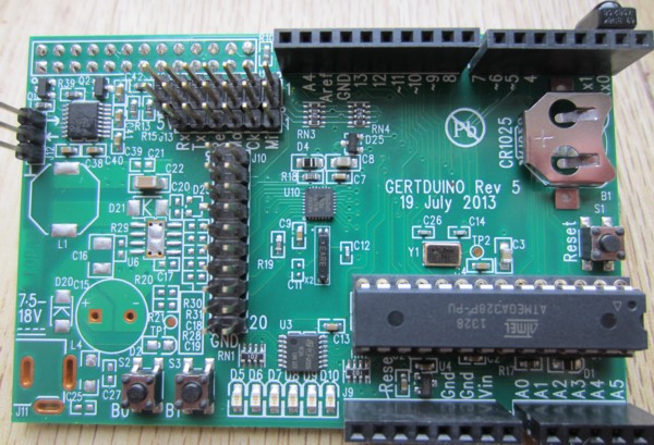
Today our GertDuino board arrived. Here are a couple of photographs of GertDuino. First of all the whole board.gertduino raspberry pi board

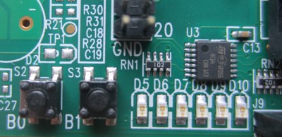
and then a zoomed in image of the user buttons B0 and B1 and LEDs D5-D10 which should prove to be very useful when making prototypes as they can be used to show system status and to accept user inputs without the need for any external components.

gertduino leds and buttons

We have some projects in the pipeline for which the GertDuino / Raspberry Pi combination will be perfect, so we will have some detailed articles on GertDuino very soon on the main REUK.co.uk website.

GertDuino for Raspberry Pi

GertDuino board to expand Raspberry Pi

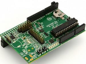
Pictured above is the new GertDuino board, developed by Gert van Loo – inventor of the popular Raspberry Pi add-on (GPIO extension) Gert Board.

The GertDuino is designed as a Raspberry Pi add-on, and gives the best of both worlds – the low power consumption and many input/output options of Arduino with the processing power and connectivity of the Raspberry Pi.

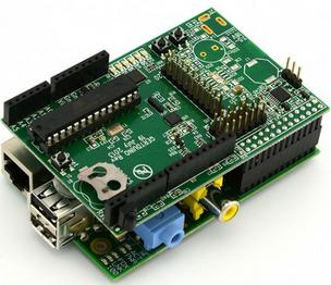
Gertduino board mounted to Raspberry PiThe image above shows the GertDuino connected to the Raspberry Pi.

The GertDuino is based around the popular Arduino Uno with a non-surface mounted ATmega328 microcontroller which can be programmed directly from the Raspberry Pi with code written and compiled on the Raspberry Pi. The GertDuino is compatible with all existing Arduino shields (Uno).

Once programmed GertDuino can be used as a standalone board or left coupled to a Raspberry Pi if the project calls for it. When connected to Raspberry Pi, it takes its 5V power supply directly from it, but as a standalone an external 5V power supply is required.

In addition to all the functionality and input/output of the Arduino Uno, a second microcontroller has been added to GertDuino (a surface mounted ATmega48) which gives an IrDA interface to the board (infrared receiver), a real time clock (with battery back up power supply – CR1025 3V button cell, not included – and high precision crystal). There is also an RS232 interface, and a couple of user push buttons and an array of six LEDs. And all this comes at a cost comparable with an original Arduino Uno board at £22.20 inc VAT available from Farnell / Element14.com.

Of most interest to us at REUK is the ability to use the GertDuino and its real time clock to wake up the Raspberry Pi only when it is needed – for example, the GertDuino could be used to monitor battery voltages or a solar water heating system, and turn on the Raspberry Pi for just a few minutes every 12 hours to process and publish the collected data. The overall power consumption of such a system would be far less than keeping the Raspberry Pi active all the time, making it much more economical to run everything from solar power. (See our article Solar Powered Raspberry Pi for details).

The user manual for GertDuino is full of information, schematics, and more on this new Raspberry Pi add-on. Click here to download and view the GertDuino User Manual (30 page PDF).

Analogue Inputs with Raspberry Pi

We have been doing a lot more work with Raspberry Pi over the last few months on some interesting projects which we will soon be covering on the REUK.co.uk website.

Raspberry Pi has an infinite number of uses and offers a great mixture of power, flexibility, and price, but it is lacking in one regard – its GPIO (general purpose input output) does not offer analogue input (ADC – analog digital converter) pins. Therefore it cannot be connected directly to non-digital temperature sensors, light detectors, or measure voltages etc. (This is in comparison to the similarly priced Beaglebone Black which offers seven  12-bit ADC pins for analogue inputs, or Arduino.)

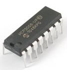
mcp3008 10 bit adc analogue to digital converter 8 channelThere are however simple and relatively cheap ways around this, one of which we will cover here: the MCP3008 10-bit 8 channel ADC pictured above. This is a microchip which can take up to 8 analogue inputs, and communicate their digital equivalent values (0-1023) to the Raspberry Pi via the SPI serial interface.

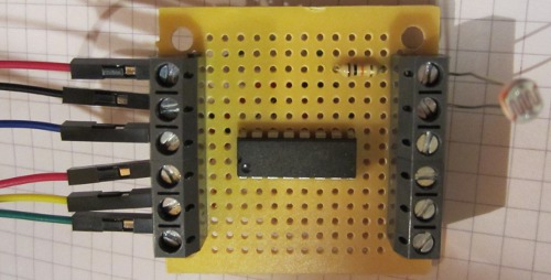
mcp3008 board to connect to raspberry pi with light detector and other analogue inputs

Pictured above is a small board we have made with the MCP3008 at its centre. Coming in on the left side are six connections to the Raspberry Pi GPIO – 3.3V and GND power connections, and the four connections for the SPI interface.

male to female jumper links for raspberry pi

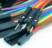
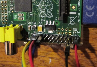
To make the connections to the GPIO we used male to female jumper links. The female end pushes over a GPIO pin, and the male end goes into a screw in terminal on our MCP3008 board.

raspberry pi GPIO analogue inputs

In order to set up the Raspberry Pi to use the SPI interface there are some commands which are required and you also need to install the SpiDev module. This is all detailed together with connection diagrams in the links to some external resources at the end of this post.

Python code for raspberry pi analogue light detector input

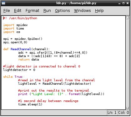
The above shows the simple Python script we used to measure the light level of a light detector connected to our MCP3008 board (making a voltage divider with the light detector and a 10K resistor and feeding the output voltage into channel 0 of the MCP3008 ADC chip. The script simply measures the light level once per second and outputs it to the terminal.

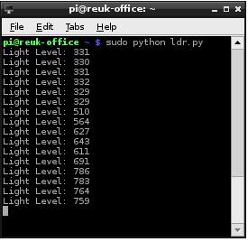
Python light detector on raspberry pi outputThe measured light level is given a digital value from 0-1023. As we wired it, higher values correspond to darker light levels, so the above screen shot shows the results as the light detector was slowly shaded.

Having got the digital value for the analog light level in the Raspberry Pi, you can do anything with it – control lights, detect dawn and dusk, control motorised curtains, log it, view it online and so on. It is also possible to use the exact same technique and MCP3008 to measure a huge range of other analogue signals including temperature sensors, voltage measurement, potentiometers, etc.

Here are links to some useful resources online to find out more information about reading analogue signals with a Raspberry Pi:

Analogue Sensors on the Raspberry Pi Using an MCP3008 – this offers comprehensive details on setting up the Raspberry Pi for SPI as well as connecting it to the MCP3008 and related Python scripts.

Analog Inputs for Raspberry Pi using MCP3008 – a guide from Adafruit.

MCP3008 Datasheet – get a better understanding of the ADC.

Temperature Sensors and USB Memory Sticks with Raspberry Pi

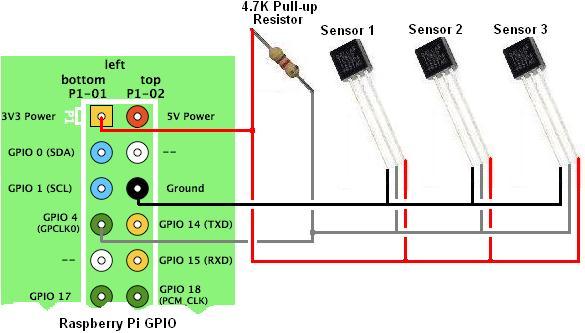
Over the last week we’ve added a few more Raspberry Pi related articles. For those of you interested in using the Raspberry Pi to make yourself a solar thermal controller or other monitoring or control system, then our article Connect Multiple Temperature Sensors with Raspberry Pi will help you to get readings from multiple DS18B20 digital temperature sensors via the GPIO on Raspberry Pi.

Connecting multiple digital temperature sensors to the Raspberry PiIf you are using your Raspberry Pi to play music and video through your television, then you will rapidly need a lot more media storage than you probably have on your operating system SD card. The cheapest and easiest way around this is to use USB flash drives. Our new article Mount USB Memory Stick on Raspberry Pi will take you through the steps required do this.

Bricking a Beaglebone Black

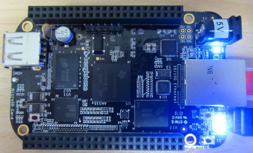
In a previous article we introduced the Beaglebone Black – a low power, low cost, credit card sized Linux computer available in the UK for around £35 and just $45 in the USA. We have been using the Raspberry Pi since it was first released in early 2012, so we were very interested to try out this similarly priced alternative which promised greater processor speed, 2GB of on board eMMC flash memory for the operating system, and most importantly for the work we do, 7 analog (ADC) inputs compared to zero on Raspberry Pi.
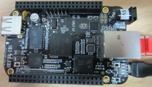
Beaglebone Black - low cost Linux computer

We received our Beaglebone Black (pictured above) around a week ago, and have been playing around with it in any spare time. Getting it set up was very quick and easy following the instructions served up as a webpage from the BBB itself. But then today something went wrong.

While looking on the internet to find any recommendations/suggestions for a VNC (virtual networked computing) server for the BBB I found this recent blog posting by Roger Meike which went through the steps he took to successfully install the X11 VNC server on his Beaglebone Black. This enabled him to interact with its full graphical interface / desktop through his Mac instead of having to hook the BBB up to a separate monitor or TV or only being able to use the command-line interface terminal via SSH.

So, step one, connect the Beaglebone Black to the ethernet cable and USB cable – check everything is working as it should via SSH.  Step two, update and upgrade the Ångstrom Linux distribution installed on the Beaglebone. So far so good – seemingly. The command opkg update took very little time to run to completion; the command opkg upgrade took the best part of an hour and a half to run, but didn’t show any errors, and after it was completed everything was working as it had previously – no problems evidenced at all.

Before embarking on the X11 VNC server installation I decided to reboot the Beaglebone Black, so I entered the reboot command. Next time I looked at the BBB a few minutes later 3 of the 4 user indicator LEDs were fixed on instead of their usual flashing. I attempted to SSH in but could not connect, and entering http://192.168.7.2 via my web browser (which is the usual way of accessing the BBB when it is connected to your computer via USB) resulted in ‘This webpage is not available’ error message.
Unresponsive Beaglebone Black after update and upgrade

It appeared that something had gone wrong somewhere, but the start up guide mentioned that the LEDs are fixed on while the eMMC is being flashed with a new distribution from the SD card and that process can take up to 45 minutes. On the off chance that upgrading the distribution without the SD card results in the same thing (and not wanting to turn it off if it was actually doing something), I left the BBB alone for a couple of hours, but the LEDs just stayed on.

I next pressed the on board reset button. The LEDs turned off, then one turned on (PWR LED), then another turned on (labelled D2), and then a few seconds later LEDs D3 and D4 turned on and stayed on permanently.
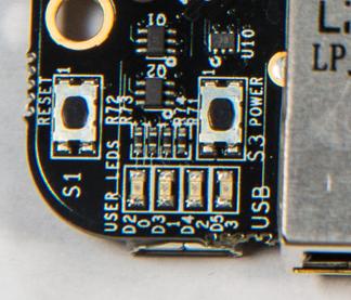
Beaglebone black user LEDs

Next I unplugged the USB cable and left the Beaglebone Black disconnected from the power that cable supplies for a few minutes. When I reconnected the USB cable to the computer, nothing happened – the computer could not see the BBB whereas it previously recognised it immediately as a USB mass storage device when it was connected. But the LEDs still came on.

I tested there was nothing wrong with the USB port on the computer – it was fine; I tried connecting the BBB to alternative USB ports on the computer, and still nothing, just the LEDs permanently fixed on.

I then hooked the BBB to a monitor via HDMI, but still nothing. It seems that it has turned into an illuminated brick.

Looking around on the internet I found this guide to unbricking Beaglebone Black without Erasing eMMC, as well as comments from other people who have run into similar problems with their BBB. It seems the only way to fix this is to download the latest Ångstrom distribution on another computer, unzip it, get an image writer for Windows, write the image to the SD card, boot from the SD card, and then wait for the image to be copied across to the eMMC. But, this requires a microSD card which I don’t have, and a lot more time. Also, quite a few stories of people going through this process and ending up with an un-bootable BBB. Is it necessary to do this every time the distribution needs updating??

I’ve never had any problems with any Raspberry Pi, and I have some which have been running continuously for months without crashing or any other issues. Therefore this bricked Beaglebone Black is going to be returned – not to be exchanged for another Beaglebone, not for a refund, but for another Raspberry Pi. Sometimes the grass is not greener on the other side – I just wish that the Raspberry Pi GPIO included some analog inputs!

As Nigel D wrote regarding the advantage of Pi over BBB: having the boot stuff and OS on removable media means that bricking the board is that much more difficult, makes it easier to experiment between different operating systems, and makes full backup and recovery easier.
Raspberry Pi Temperature Datalogger with DS18B20 Sensor

We’ve been adding more Raspberry Pi related articles to the REUK.co.uk website over the last week covering GPIO – connecting sensors to the Pi, and also controlling relays connected to the Pi from the internet

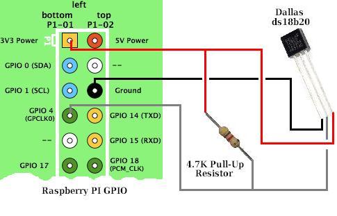
Raspberry Pi GPIO DS1B20 temperature sensor connectionsNow we have moved on to cover temperature sensors, a very important part of the work we do relating to solar water heating systems. Being able to control a pump based on the temperature of one or more sensors is very powerful, but Raspberry Pi makes it (relatively easy) to also monitor those sensors over the internet and track the exact state of the system in real time remotely while also logging the data.

We have recently added this article on using the DS18B20 1-wire digital temperature sensor with Raspberry Pi: DS18B20 and Raspberry Pi. (Note that Raspberry Pi only has digital, no analog inputs – therefore we use digital temperature sensors with Pi rather than the analog LM335 temperature sensors we use with our primary solar water heating pump controller product.)

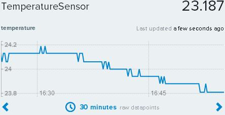
Raspberry Pi temperature data logger with Xively

We also added a second article which shows how you can feed the temperature readings from the DS18B20 connected to the Raspberry Pi for to be logged and visualised by cloud service Xively: Raspberry Pi Temperature Datalogger with Xively.

When we have finished publishing these introductory Raspberry Pi articles, we’ll then move on to articles showing how to pull the techniques explored together to make renewable energy related devices with Raspberry Pi – e.g. wind speed dataloggers, solar controllers, energy monitors, energy saving automation devices, and much more.