Raspberry Pi Home Automation with Machinon

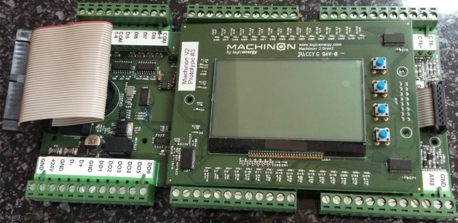
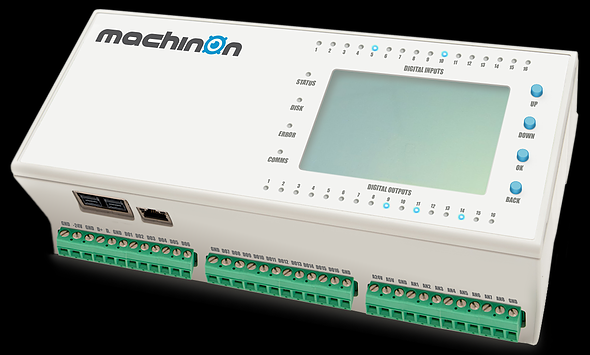
Pictured below is Machinon, hopefully soon to be released industrial-grade hardware originating from a community project, and designed to manage home and small business automation with a Raspberry Pi.

machinon home automation iot raspberry piThis smart home solution adds smart IO to a Raspberry Pi – 16 digital inputs, 16 digital outputs, and 8 analogue inputs.

The digital inputs can be used as pulse counters (for kWh meters etc) or to detect status changes (doors opening and closing, buttons being pressed, motion sensors triggered etc).
The analogue inputs (0 to 20mA, 4 to 20mA, and 0 to 10V input with 14bit resolution) can be used to measure currents and voltages, light levels, temperatures, and more.
The digital outputs each supply up to 500mA which can be used to switch high voltage and high current appliances via a relay, or directly power low current low voltage devices.

Machinon utilises two ATxmega microprocessors which take care of all the complex pulse counting, timing, analogue measuring, and data collection. The Raspberry Pi then simply communicates with Machinon via UART (serial port) to grab data and control and configure the smart IO.

machinon smart home prototype internals

Machinon is designed to interface with many open source home automation software packages including Domoticz, openHAB, and HomeGenie so the overall user experience should be relatively simple.

The price of this device is likely to be around £200 plus the cost of a Raspberry Pi and microSD card to go in it. Therefore, probably under £250 all in including delivery.

machinon smart home with raspberry pi

For more information, click here to visit the Machinon website.

Testing 128×32 OLED IIC Display with Arduino

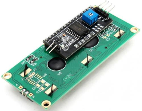
Many of the products we sell make use of 16×2 character LCD displays. These displays coupled with an Hitachi HD44780 LCD control module enable an Arduino or Raspberry Pi to operate the display very simply with just two data connections and two power connections required.

16x2 LCD display with module for use with Arduino and Raspberry Pi

However, these displays are physically quite large being 80 x 36mm, and while they are well suited to panel mounting, they cannot really be attached to the circuit board that is driving it without creating a device with large dimensions.

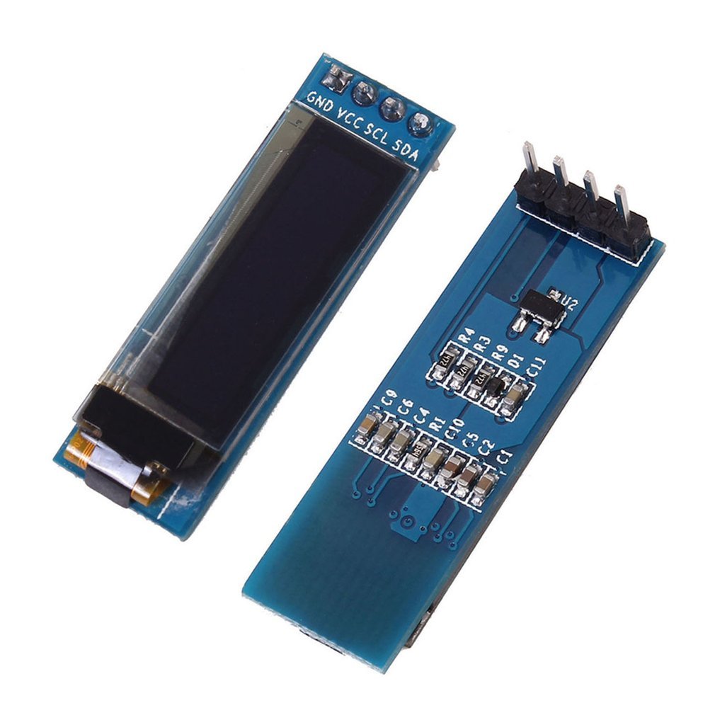
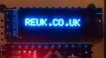
We have recently being looking at alternatives to these displays looking for something physically smaller, easily circuit board mountable, lower power consumption, and improved contrast. After much testing, we have chosen the OLED display pictured below.128x32 i2c arduino displayThese displays are far smaller having an active screen area of just 22.38 x 5.58mm. They require no backlight as each of the 128×32 pixels self-illuminates thanks to OLED technology. The maximum power consumption of one of these displays is 0.08W with every pixel illuminated – therefore less when showing text or when nothing is being displayed. In all ways these displays are an improvement on the 16×2 character LCDs.

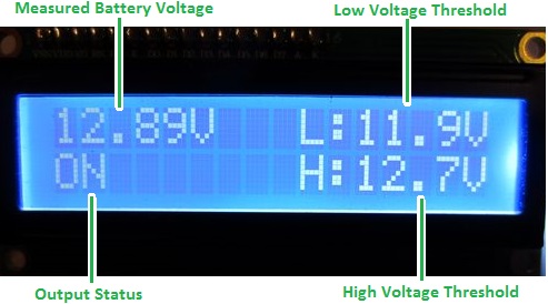
OLED display used with arduinoThese OLED displays have much better contrast than LCDs, there is more space available to display information since more characters can be displayed, and there are much better graphics capabilities with the OLED displays. The image above shows the new OLED version of the LCD display from our REUK Low Voltage Disconnect with Display pictured below.

LCD display on REUK low voltage disconnect (LVD)

The biggest advantage however is the ease with which these OLED displays can be mounted to the circuit boards of our controllers so that we can produce more convenient small form factor integrated units with no increase in our pricing for customers.

arduino pro mini controlled 128 x 32 oled display

If you are interested in trying out one of these displays for your own projects, click here: buy 128×32 OLED Display for under £3 including delivery. If you intend to use one with an Arduino project, you will need to add the following libraries to your Arduino IDE: SSD1306 Library and Adafruit GFX Library, so that you can communicate with the display.

Thermostat with Datalogger and LCD Display

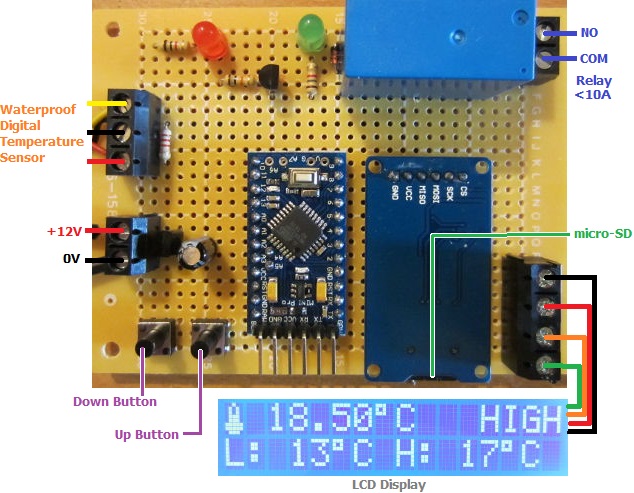
Pictured below is a thermostat we have just completed which includes an LCD display and temperature datalogging to a micro-SD card.

Cooling thermostat with LCD display and SC card dataloggerThis will be used to control and monitor a small (4′ x 4′ x 6′) shed cooling system. The cooling parts of a second hand fridge have been mounted to an inside wall of the shed, and this thermostat with its digital temperature sensor and relay is used to turn the cooler on and off as and when required to keep the shed cool.

The display shows the current temperature of the shed and the system status. The user can set the high temperature and low temperature thresholds at which the cooler will be turned on and off respectively; and their chosen thresholds are displayed on the bottom line of the display.

Every 30 seconds the temperature of the sensor and the cooler status (on=1, off=0) are logged (written to a csv text file on a micro-SD card) for later analysis on a computer using Excel or similar.

If you need something similar to this, or anything else utilising temperature datalogging, monitoring, and control, email neil@reuk.co.uk with details of your requirements.

Spark Core Introduction and First Impressions

Spark Core is described as an Open Source IoT (Internet of Things)Toolkit.  It is a small Wi-Fi development board which connects automatically to servers in the cloud, and can be programmed and controlled remotely over the internet and also send data to the cloud where you can access it.
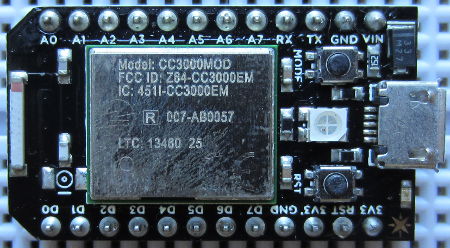
Spark Core Wi-Fi Open Source IoT development board

The Spark Core board is programmed using Wiring – the same programming language used with Arduino – but via a browser based IDE. Therefore you do not physically connect the board to your PC. Instead you just power it, it connects to your Wi-Fi automatically (with credentials entered during a one off setup process), and then automatically connects to the Spark servers. You then write your Wiring code in your web browser, it is checked and compiled on the Spark servers and the code is then flashed to your board over Wi-Fi and starts running.

Each Spark Core has a unique device ID with an associated secret access code so no-one else can take over your Core or access the data from it.

To try out Spark Core, we put together a very simple setup just to measure the ambient light level.
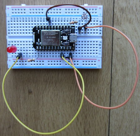
Spark Core light detector test circuit

Spark Core is supplied with its own prototyping breadboard. We connected a light dependent resistor (LDR) to one of the regulated 3.3V output pins, and to one of the ground pins via a 10K resistor. This creates a voltage divider (where the LDR meets the resistor), the output of which we connected to analog pin A4. (In the photograph above, we also have an LED connected via a current limiting resistor to digital pin D0).

The analog pins on the Spark Core are 12-bit analog to digital converters (ADC). Therefore, they measure the voltage on the pin and give it a proportional digital value from 0 to 4095 where 0 is 0V and 4095 is 3.3V.

const int ldrpin = A4;
int lightlevel = 0;

void setup(){
   pinMode(ldrpin, INPUT);
   Spark.variable("lightlevel", &lightlevel, INT);
}

void loop(){
   lightlevel = analogRead(ldrpin);
}

Above is the Wiring code we wrote to continuously save the digital conversion of the measured voltage on pin A4 (here called ldrpin), as a variable lightlevel. Defining the Spark.variable lightlevel in setup makes it accessible via the Spark servers.

With that code flashed to the Spark Core and running, you can now instruct the Spark servers to grab that variable (with the Spark API). The simplest way to grab the lightlevel variable is to enter a URL in your web browser like this:

https://api.spark.io/v1/devices/YOURDEVICEID/lightlevel?access_token=YOURACCESSCODE

…obviously substituting in the device ID and access code for your own Spark Core. The browser will then display something like this:

{
  "cmd": "VarReturn",
  "name": "lightlevel",
  "result": 2961,
  "coreInfo": {
    "last_app": "",
    "last_heard": "2014-08-03T11:21:32.577Z",
    "connected": true,
    "deviceID": "YOURDEVICEID"
  }
}

So, in this example the light level was measured by the Spark Core to be 2961 (meaning that the voltage on the pin was 3.3*(2961/4095) Volts).

Instead of measuring a light level, we could have connected any other digital or analog sensors – temperature sensors for example – pre-processed the collected data on the Spark Core board to be saved as useful values which we could view from anywhere in the world.

For a final test, we wrote a very short Python script on an internet connected Raspberry Pi to grab just the value of lightlevel out of the file returned by Spark and to print it out.

#!/usr/bin/python
import urllib2
import json
response = urllib2.urlopen('https://api.spark.io/v1/devices/YOURDEVICEID/lightlevel?access_token=YOURACCESSCODE
html = response.read()
reading = json.loads(html)
lightlevel = reading['result']
print lightlevel

This was saved as file core.py and run using the command sudo python core.py in the terminal. In under one second, the value of the light level measured on the Spark Core was displayed. With a slightly more complex Python script or using cron the light level could be checked every 5 minutes or other interval and logged to a file for later analysis etc.

All in all, first impressions of Spark Core are very favourable. While we have previously used ethernet shields with Arduino to enable remote control and monitoring over the internet, this has necessitated messing around with broadband router settings and firewalls etc. With Spark Core everything happens automagically which makes things a lot simpler for the average user and opens up many Internet of Things possibilities.

Click here to visit the Spark.io website for more information about Spark Core.
Project of the Day – Thermostat Controller for Innovative AC Cooler

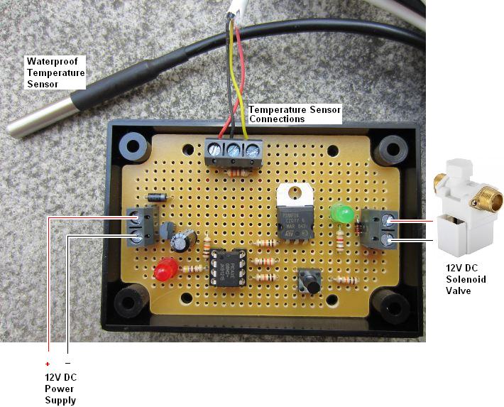
Today we have worked on a thermostatic controller which is used to open a solenoid valve when the temperature measured by a sensor exceeds a user set level.

programmable thermostat to control a 12V DC solenoid valve

This controller is for a telecoms company which have servers in a data centre which are cooled by air conditioning (AC). The AC units are located outside an office in an area from which heat cannot escape, and so it builds up eventually causing the AC units to fail.

Four years ago when we first heard from this company, they had set up a Hozelock irrigation system on a timer to spray water mist around the AC units from 8am to 7pm on workdays, but they wanted something thermostatically controlled so that water would only be used to cool the AC units when it was actually necessary.

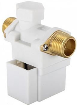
12 volt dc solenoid valveWe provided them with a complete solution including enclosure, 12VDC solenoid valve, controller, and a waterproof temperature sensor (an LM335 we sealed with epoxy into stainless steel tubing – the method for its manufacture is explained here: Make a Waterproof Temperature Probe). This has worked very well ever since reducing the peak temperature of the data centre by 6 degrees Celcius. However, after 4 years in all weathers the temperature sensor has started to become unreliable, and the company also wanted some modifications to the programming of the controller so that the water mist can be triggered at lower temperatures.

The new controller which was pictured above now uses a commercial waterproof DS18B20 digital temperature sensor and we also substituted a MOSFET for the relay which was on the original unit so that the whole controller is now solid state. This controller should help to keep the AC units cool for a good few years to come.

The use simply uses the button on the controller to set the threshold temperature above which the misting is to be turned on (settable in 1 degree steps from 25 degrees Celcius). After 10 seconds of the temperature being measured over this threshold the misting will start, and it will run until the temperature falls by a couple of degrees.

Reducing Reflectivity of PV Solar Panels to Increase Efficiency

The US Department of Energy’s National Renewable Energy Laboratory (NREL) is carrying out research on reducing the reflectivity of PV solar panels to increase their efficiency.

Standard silicon solar cells (out of which solar panels are built) reflect around 35% of all the light which hits them – therefore one third of the solar energy hitting them is immediately lost. To reduce these losses, commercial solar cells receive an anti-reflective coating (gas molecule deposition) which brings down reflectivity to 7-10% typically. (It is this coating which makes solar cells appear blue). This process is toxic and the equipment used to achieve it is very expensive. Therefore NREL are looking at ways to reduces reflectivity of solar cells while at the same time reducing costs of manufacture.

NREL Natcore technology black silicon solar cellNREL’s solution called black silicon uses an acid bath with a silver nitrate catalyst to put trillions of tiny holes into the surface of each 6×6 inch solar cell. These holes trap the photons of sunlight increasing the chance they will be absorbed by the solar cell and converted into electricity. With this technique reflectivity is reduced to less than 1.5% (which results in solar cells which appear black).

An added benefit is that solar cells treated in this way perform better in the morning and afternoon when the angle of the sun is further from the optimum (perpendicular), and they also perform well in overcast conditions.

NREL black silicon under microscopeNREL have exclusively licensed this black silicon technology to Natcore Technology  specialists in thin film solar panel manufacturing. With further development they hope to make more efficient and cheaper solar panels than anything on the market today.