REUK Shop > Low Voltage Disconnects
Additional Information
This device (new for 2017) is designed to protect a 12V battery or battery bank from being run down excessively and suffering permanent damage. It is based around our original 12V LVD with display, but with the added benefit of a datalogger which shows minimum, maximum, and average voltage measured on your battery. This new version is also easier to set up and programme with your desired voltage thresholds.
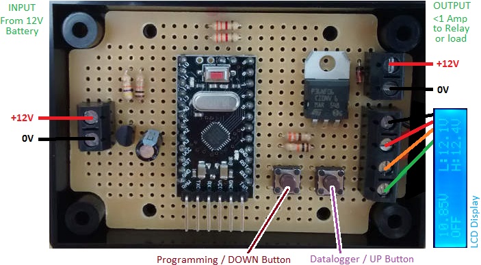
The output from this low voltage disconnect is rated to 1 Amp. This can be used to directly power lighting and other devices up to a total of 1 Amp, or can be used to energise a relay which in turn can switch much higher current levels. (see here for information on relay boards to switch up to 10 or 16 Amps, or here for information on automotive relays to switch up to 30 or 40 Amps.
The user can programme the voltage below which the low voltage disconnect will engage (turning off the output and therefore disconnecting the loads to protect the battery), and also programme the voltage above which the output will turn back on again reconnecting the loads.
To ensure brief spikes and dips in voltage are ignored, the measured battery voltage must remain below the low voltage threshold for 10 seconds continuously before the disconnect engages. The voltage must subsequently remain above the high voltage threshold for 10 seconds continuously before the disconnect will be cancelled and the loads reconnected.
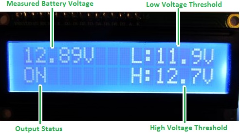
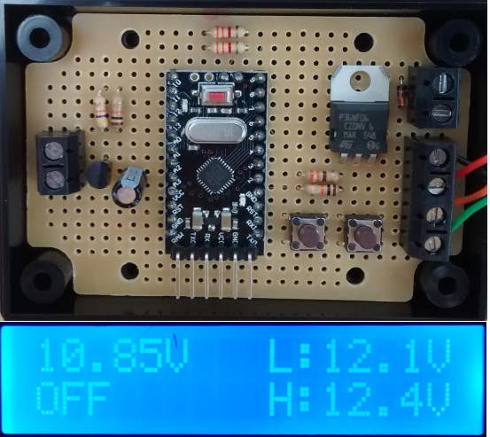
The LCD display unit is backlit and shows the measured battery voltage, the system status, and the user-programmed high and low voltage thresholds. The backlight is also used to give a visual indication (by blinking) when the system state may be about to change.
Low Voltage Disconnect Programming Instructions
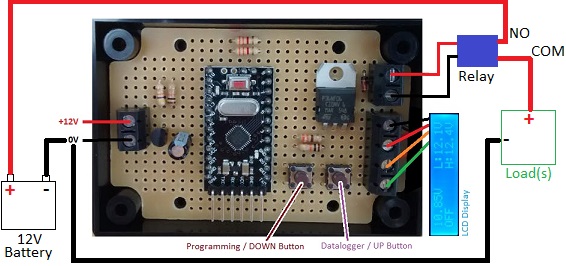
Connect the controller circuit board to the 12V battery and to the LCD display as shown in the connection diagram above.
To programme in your voltage thresholds, press and hold the programming button on the circuit board. The backlight on the display will turn off. If you keep holding the button for 3 seconds, the backlight will turn back on and the display will show PROGRAMMING MODE -RELEASE BUTTON-.

You are now in programming mode, so release the button.

The display will now show the current value of the low voltage disconnect voltage. You can use the up and down buttons to increase or decrease this in 0.1 Volt steps until you get to your desired value. Five seconds after the last time you press the button, whatever value is displayed will be stored in memory as your new low voltage disconnect voltage.
The screen will now show Low Voltage Saved XX.XV (where XX.X is the voltage you set).
After a couple of seconds the display will show Set High Voltage followed by the currently saved value for the high voltage cancellation voltage (the voltage the battery has to reach before the disconnect will be cancelled). If the previously saved value is less than 0.3V higher than the disconnect voltage, the controller will automatically set the cancellation voltage to be the disconnect voltage plus 0.3V. The cancellation voltage must always be at least 0.3V higher than the disconnect voltage, and this device will not allow you to set the difference to anything less.
You can now use the up and down buttons again to increase or decrease the cancellation voltage in 0.1V steps until you get to your desired value. Five seconds after the last time you press the button, whatever value is displayed will be stored in memory as your high voltage cancellation voltage.

The screen will now show High Voltage Saved YY.YV (where YY.Y is the voltage you set).
The thresholds you programme in are stored in long term memory and so are NOT lost if/when you disconnect the device from the battery. Therefore you only need to go through these programming steps when you actually want to change the thresholds.
Using the REUK Low Voltage Disconnect with Display and Datalogger
With programming out of the way, everything is very simple. If the voltage falls below the low voltage threshold, the backlight of the display will blink. The system status will change to LOW, but the output will remain on. If after ten seconds the battery voltage is still measured to be low, then the system status will change to OFF, the output will turn off, and the display backlight will stop blinking.

When the battery is recharged or recharging and exceeds the high voltage threshold, the system status will change to HIGH, the display backlight will start to blink, but the output will remain off. If after ten seconds, the battery voltage is still above the high voltage threshold, then the system status will change to ON, the output will turn on, and the backlight will stop blinking.

If when the device is first connected to the battery, the measured voltage is immediately found to be below the low voltage threshold, the device will start in the OFF position – i.e. output off, system status OFF.
Datalogger
In order to access the datalogger feature of this device, press the Datalogger Button for half a second. The display will then show the minimum, maximum, and average voltage of the battery as recorded by the datalogger since it was last cleared by the user.
In the example screen shot above, the minimum measured voltage was 12.35V, the maximum was 14.52V, and the average (arithmetic mean) was 12.73V.
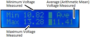
The datalogger data will remain on display for around 30 seconds, or until the Datalogger Button is pressed again for half a second.
To permanently erase all data from the datalogger, press the Programming Button for half a second while the datalogger is on the display. PRESS AGAIN TO CLEAR DATALOG will be displayed.
Press the Programming Button once more within three seconds and the display will show DATALOG EMPTY. Do nothing, and the display will return to the datalogger without any data being deleted.
Note that once the datalog has been cleared, the previously stored data is permanently deleted and cannot be recovered.
The battery voltage is measured multiple times per second and stored in short term memory over the course of an hour. At the end of the hour, the collected data is written to long term memory where it remains even if the power to the controller is cut. Therefore, if you must disconnect the power from this controller, you will lose only up to one hour of the most recently collected data.
Technical Notes The reason the data is not written directly to long term memory after every temperature measurement is that this EEPROM (Electrically Erasable Programmable Read-Only Memory) built into the microcontroller has a specified minimum life of 100,000 write/erase cycles. Write to the same location in memory once per second and it could be worn out and unable to retain data properly within just a few days! By writing the data only once per hour, the usable lifetime of the memory for the datalogger will be measurable in decades.
Bespoke Low Voltage Disconnects
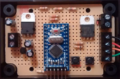 If you have any questions about the above instructions please email neil@reuk.co.uk. Similarly email if you have slightly different requirements – for example, if you want a low current relay fitted to the circuit board in place of the 1A output, if you want to have a low voltage disconnect with datalogger, or if you want a 24V low voltage disconnect with display (pictured above).
